When you deal with diode or transistor components such as LED, 7 Segment display, RGB LED, etc., you need to understand whether the component is common anode or common cathode, it will give you completely different result.
7 Segment Display

Let’s us the 7 Segment display as example.
All a – g & dp are connected to a ‘common’. When the common is common anode, we need to connect this to a high voltage, sometime 5V, so that current will be generated when a – g & dp is LOW. On the other hand, if the common is common ground, we need to connect this to a low voltage, most of the time is ground, so that current will be generated when a – g & dp is HIGH.
Common anode – the segment will be lit if the signal pins a – f & dp is LOW
Common cathode – the segment will be lit if the signal pins a -f & dp is HIGH.
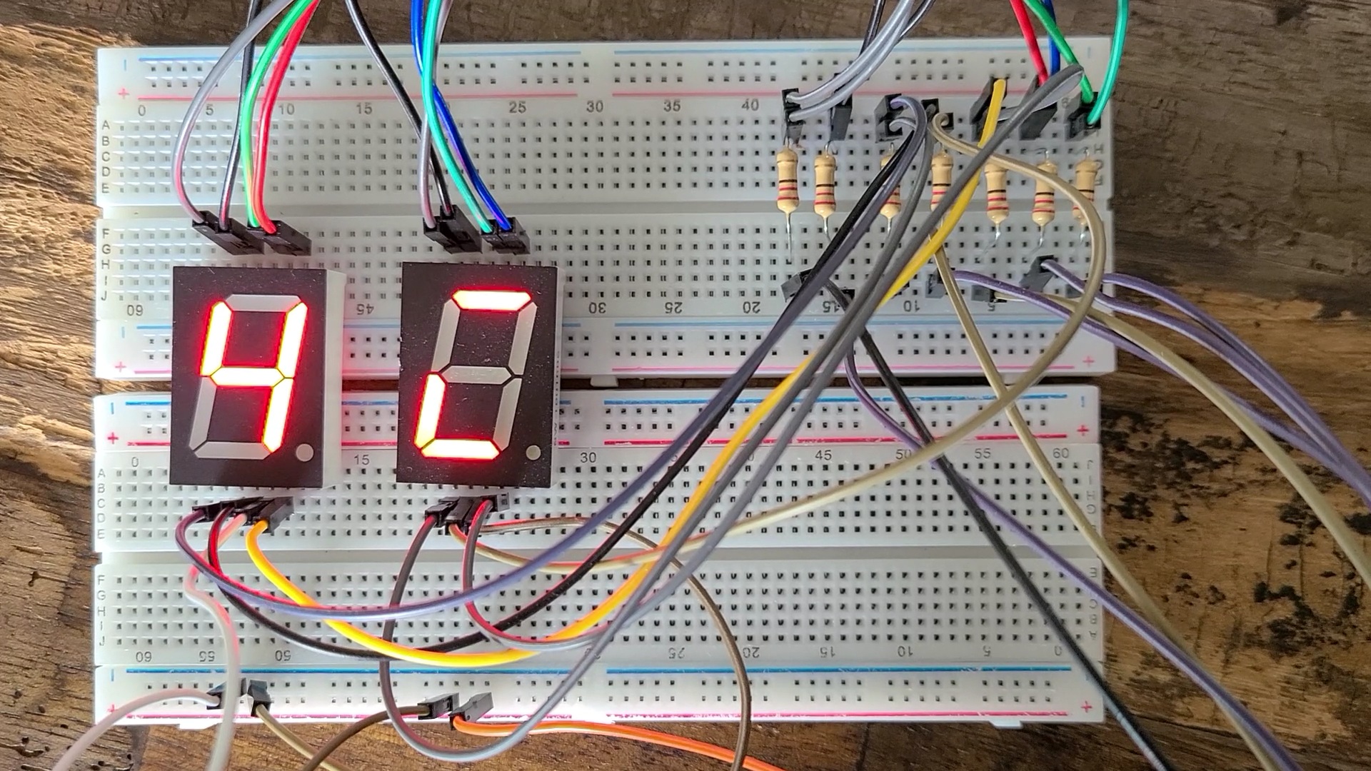
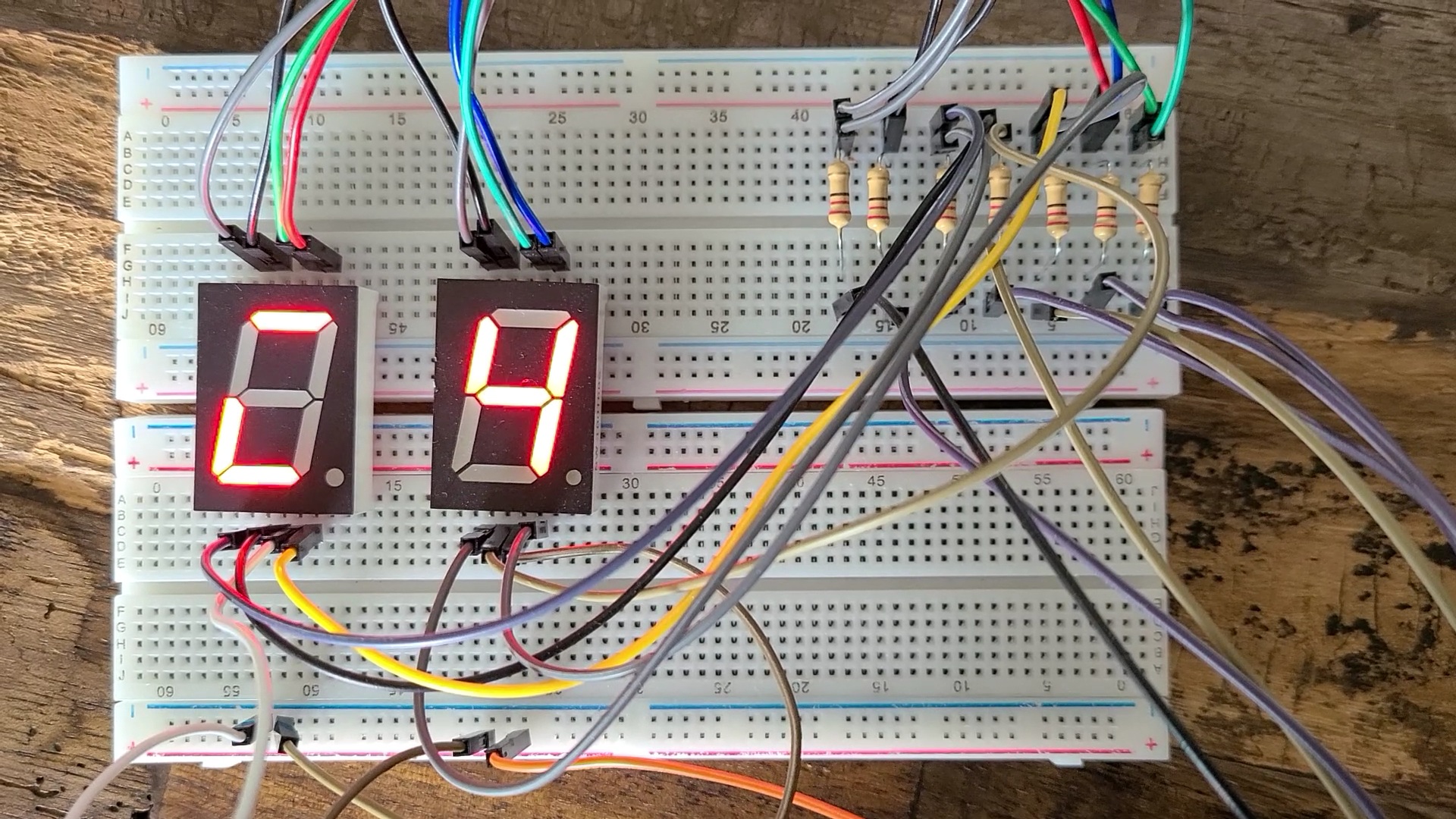
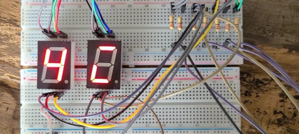
As you can see from the above photos, left display is common cathode and right one is common anode. When we display a number 4 to the common cathode display, it will give the opposite result from the common anode. If you display a number 4 in the common anode device, it will give the same opposite result in common cathode device.
Switching between 1 & 0
So, when you develop the program, you need to understand what device is going to use. Otherwise, you need to do some switching between 1 & 0, just like the program below.
int start_pin = 2;

void setup() {
  // put your setup code here, to run once:
  int p;
  for (p=start_pin; p<start_pin+7; p++){
    pinMode(p, OUTPUT);
  }
}

void loop() {
  // put your main code here, to run repeatedly:
  int i = 0;
  int j = 0;
  int number = 0;
  int d = 0;
  int segment = 0;
  const int number_array[][10]={{1,1,1,1,1,1,0},
                                {0,1,1,0,0,0,0},
                                {1,1,0,1,1,0,1},
                                {1,1,1,1,0,0,1},
                                {0,1,1,0,0,1,1},
                                {1,0,1,1,0,1,1},
                                {1,0,1,1,1,1,1},
                                {1,1,1,0,0,0,0},
                                {1,1,1,1,1,1,1},
                                {1,1,1,0,0,1,1}
                                };

  for (number=0;number<10;number++){
    for (d=0;d<100;d++){
      for (segment=0;segment<8;segment++){
        digitalWrite(start_pin+segment, number_array[number][segment]);
      }
    delay(10);
    }
  }

  for (number=0;number<10;number++){
    for (d=0;d<100;d++){
      for (segment=0;segment<8;segment++){
        digitalWrite(start_pin+segment, not number_array[number][segment]);
      }
    delay(10);
    }
  }
}
This program is developed with common cathode assumed, the number_array with 1 is on, 0 is off, i.e. 4 is 0110011. When apply the same pattern to the common anode device, it will look like ‘1001100’, the monster you see in those picture.
So, we add a ‘not’ to the line we highlighted in the code, it will give the opposite value to the pin, i.e. 1 -> 0, 0 -> 1. Thus, the data output of 4 will be changed from ‘0110011’ to ‘1001100’, it will be 4 in the common anode but a monster in common cathode.
RGB LED
7 segment is quite easy to hand. But, take a look of RGB LED. I would prefer using common cathode RGB LED, because it is easy for me just follow the color code. But for common anode one, you need to do something like 255 – the color code as shown below, have a try!
  analogWrite (red, 255 - 232); # Color code 232, 97, 0 (E86100)
  analogWrite (green, 255 - 97);
  analogWrite (blue, 255 - 0);
  delay(1000);

  analogWrite (red, 255 - 199); # Color code 199, 128, 35 (C78023)
  analogWrite (green, 255 - 128);
  analogWrite (blue, 255 - 35);
  delay(1000);