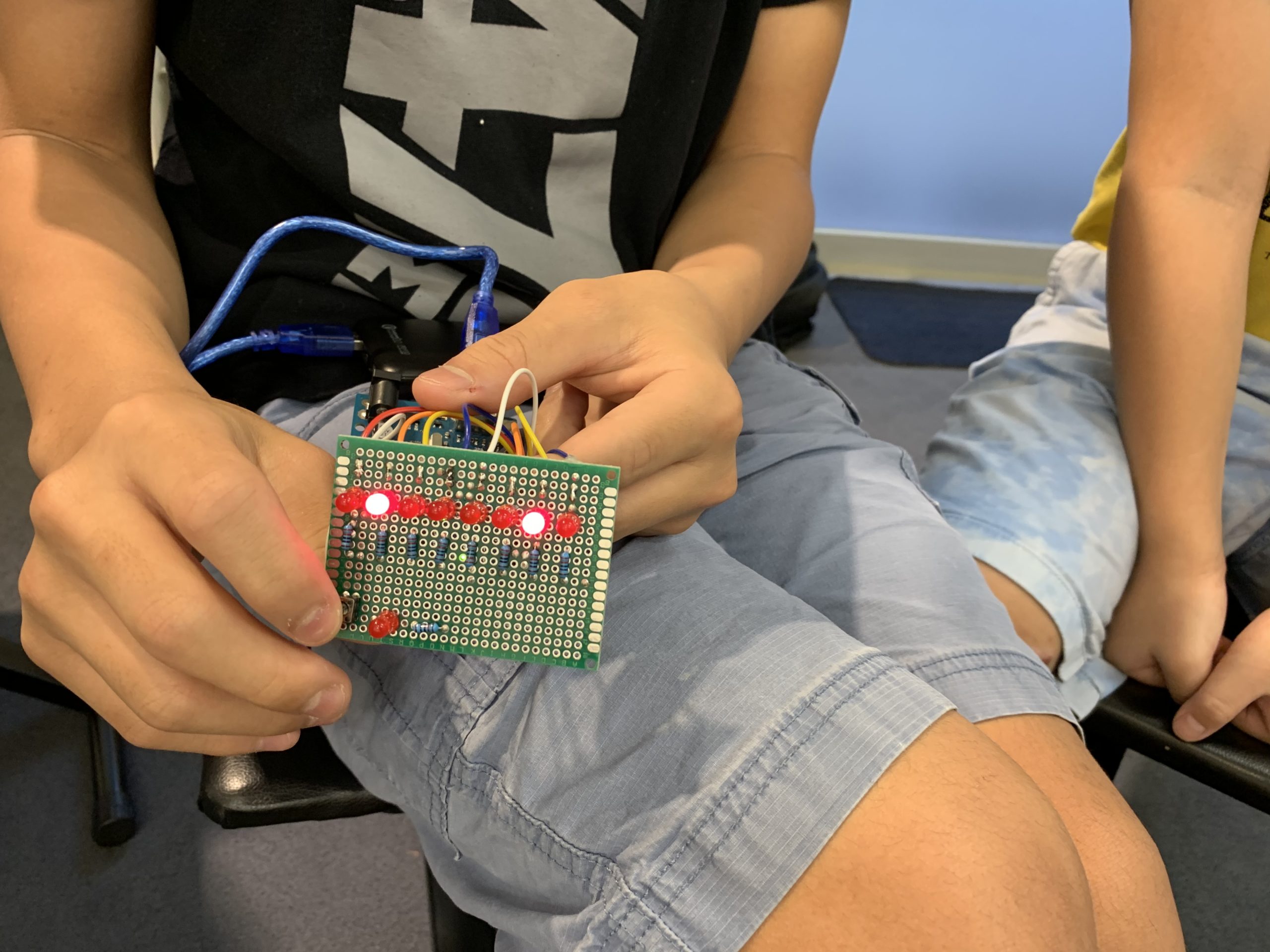
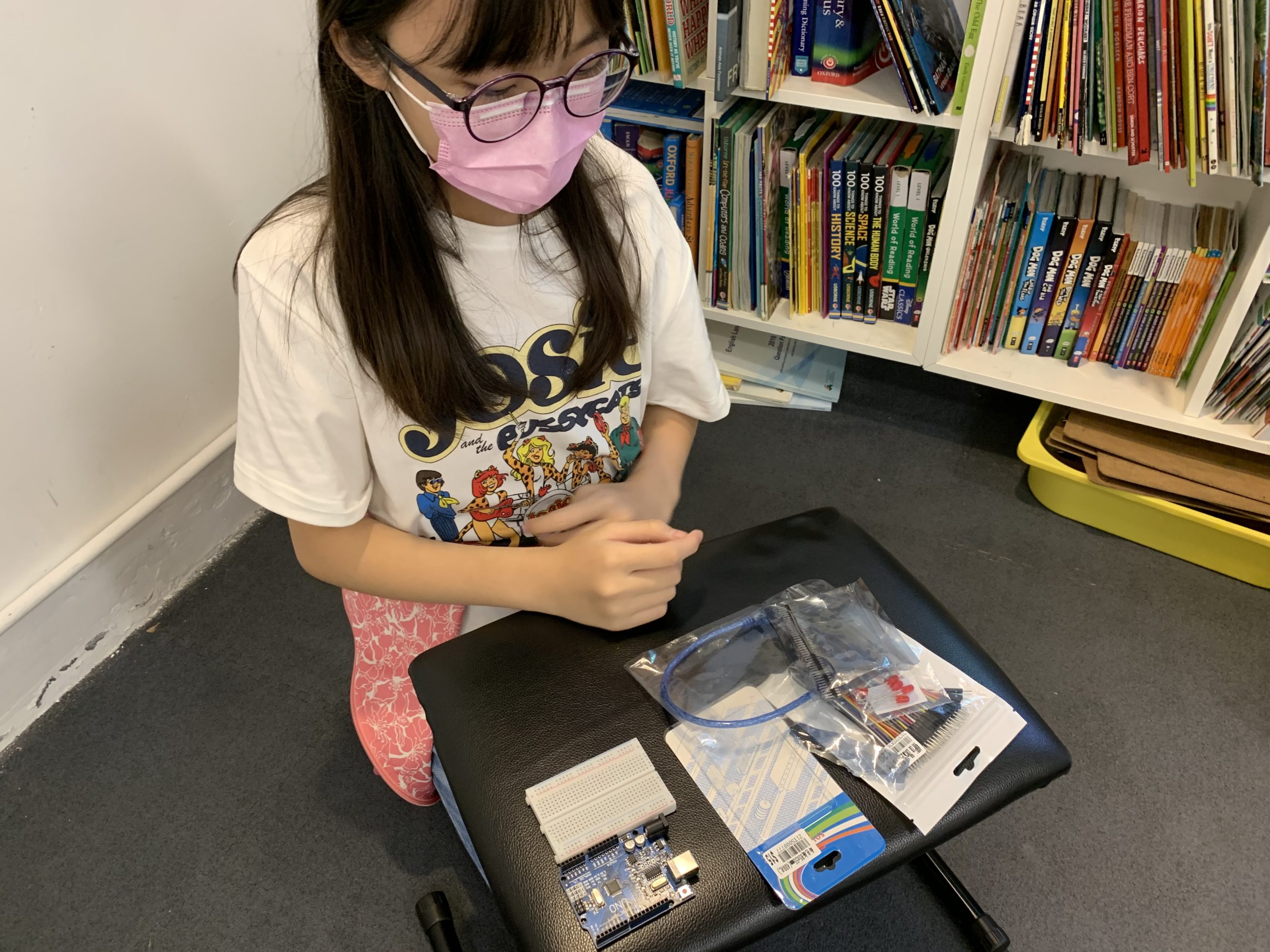
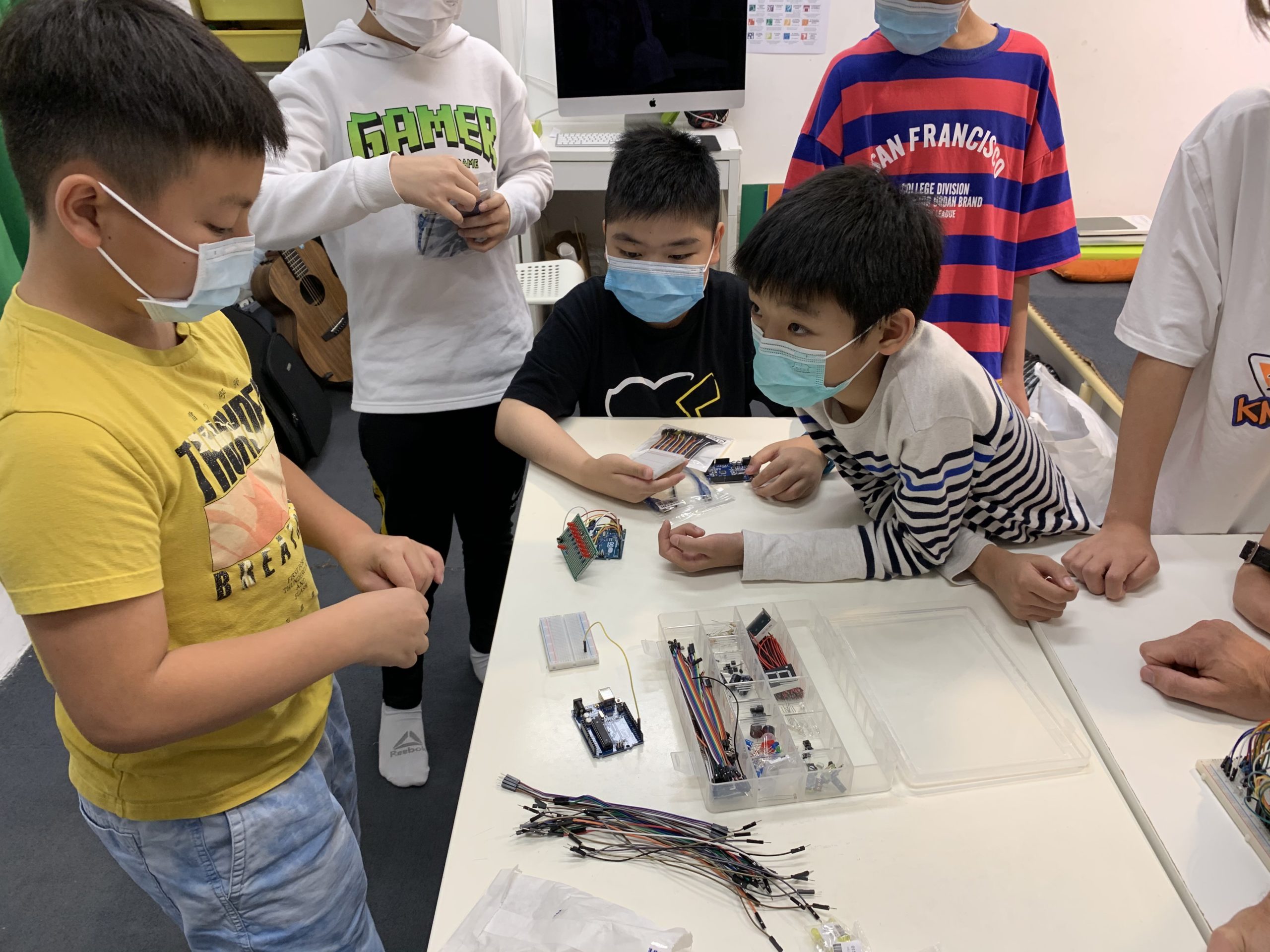
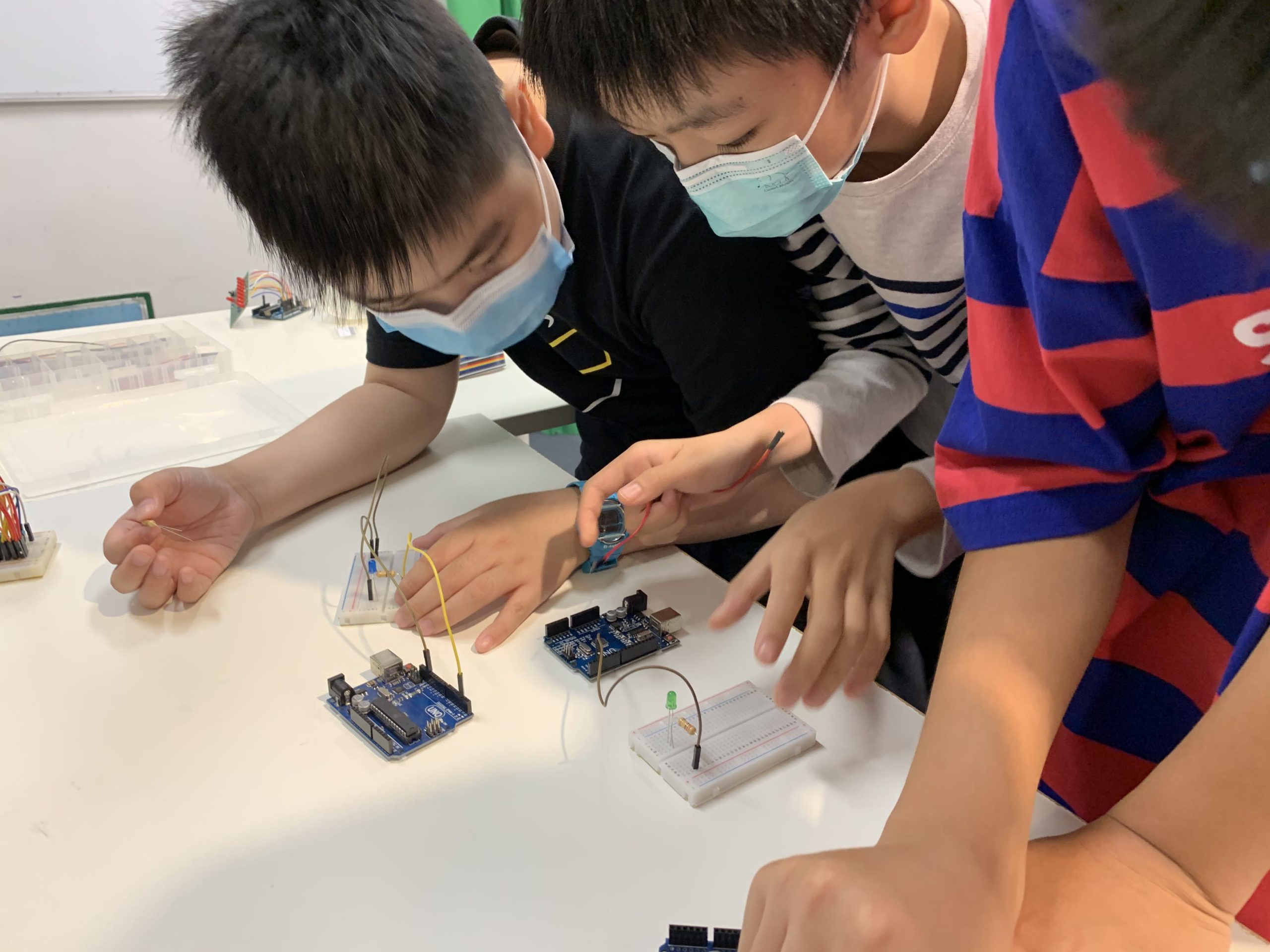
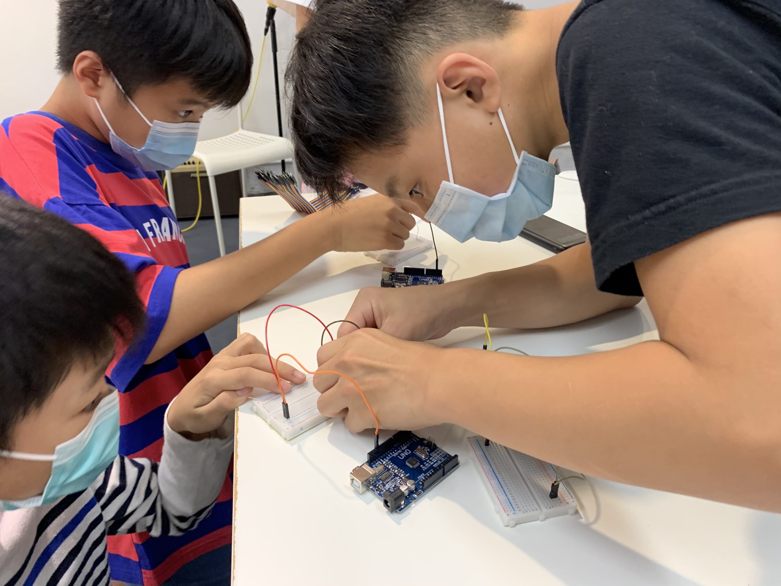
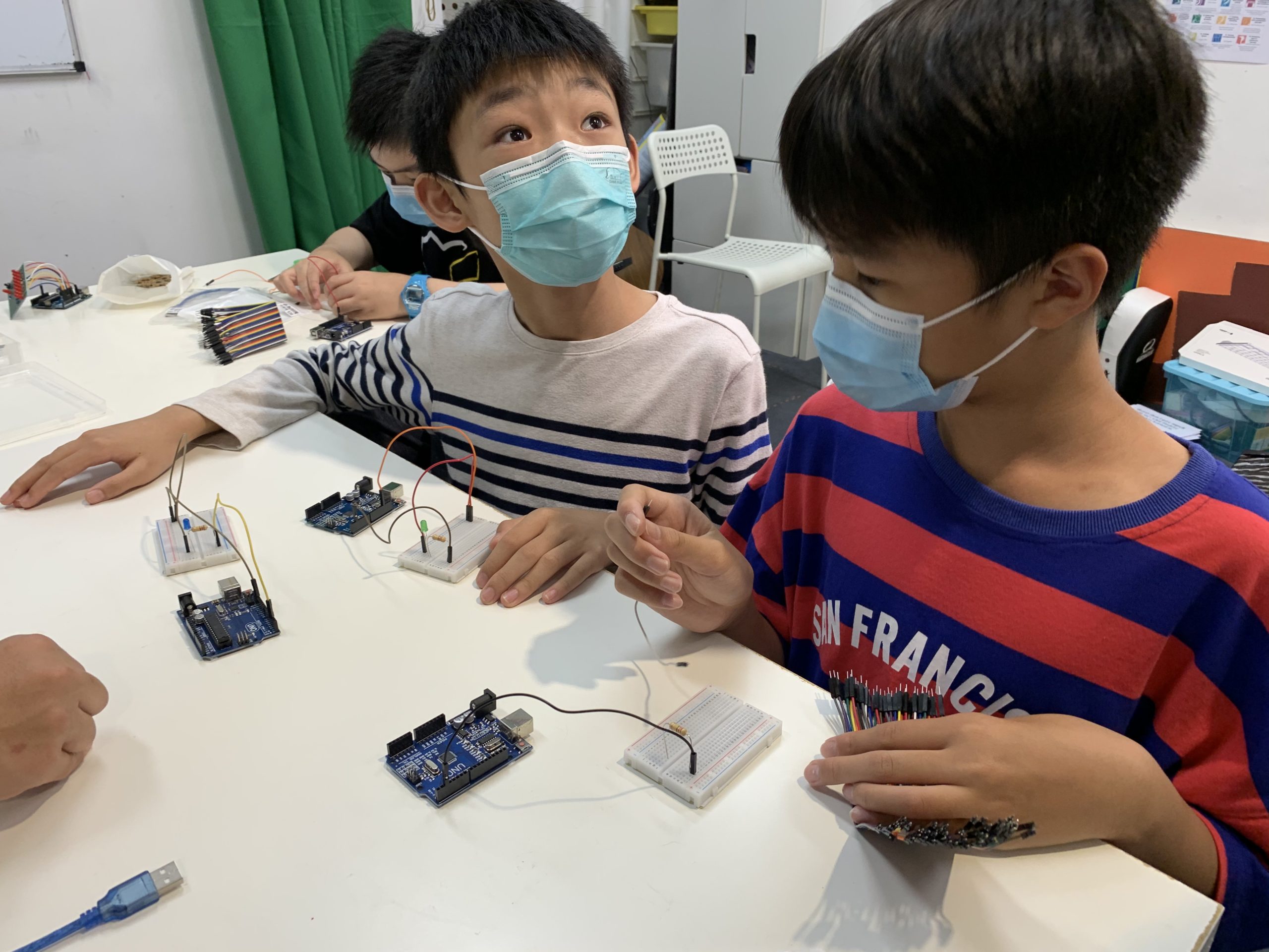
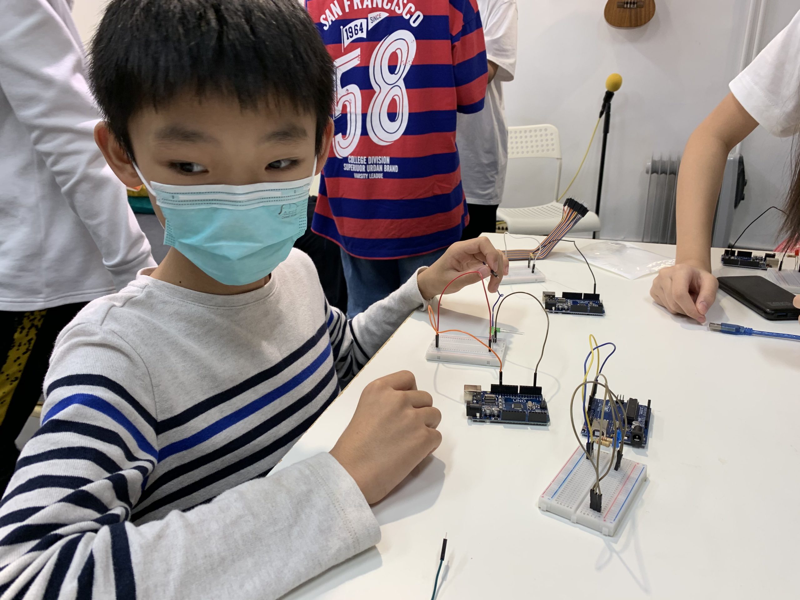
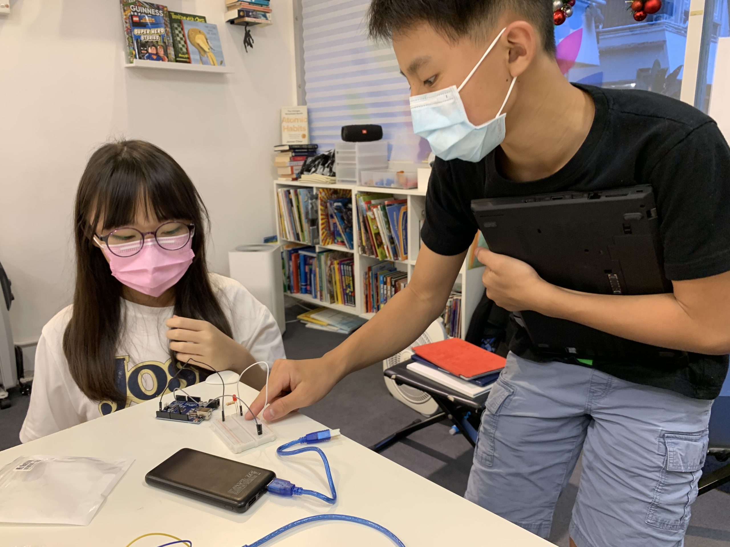
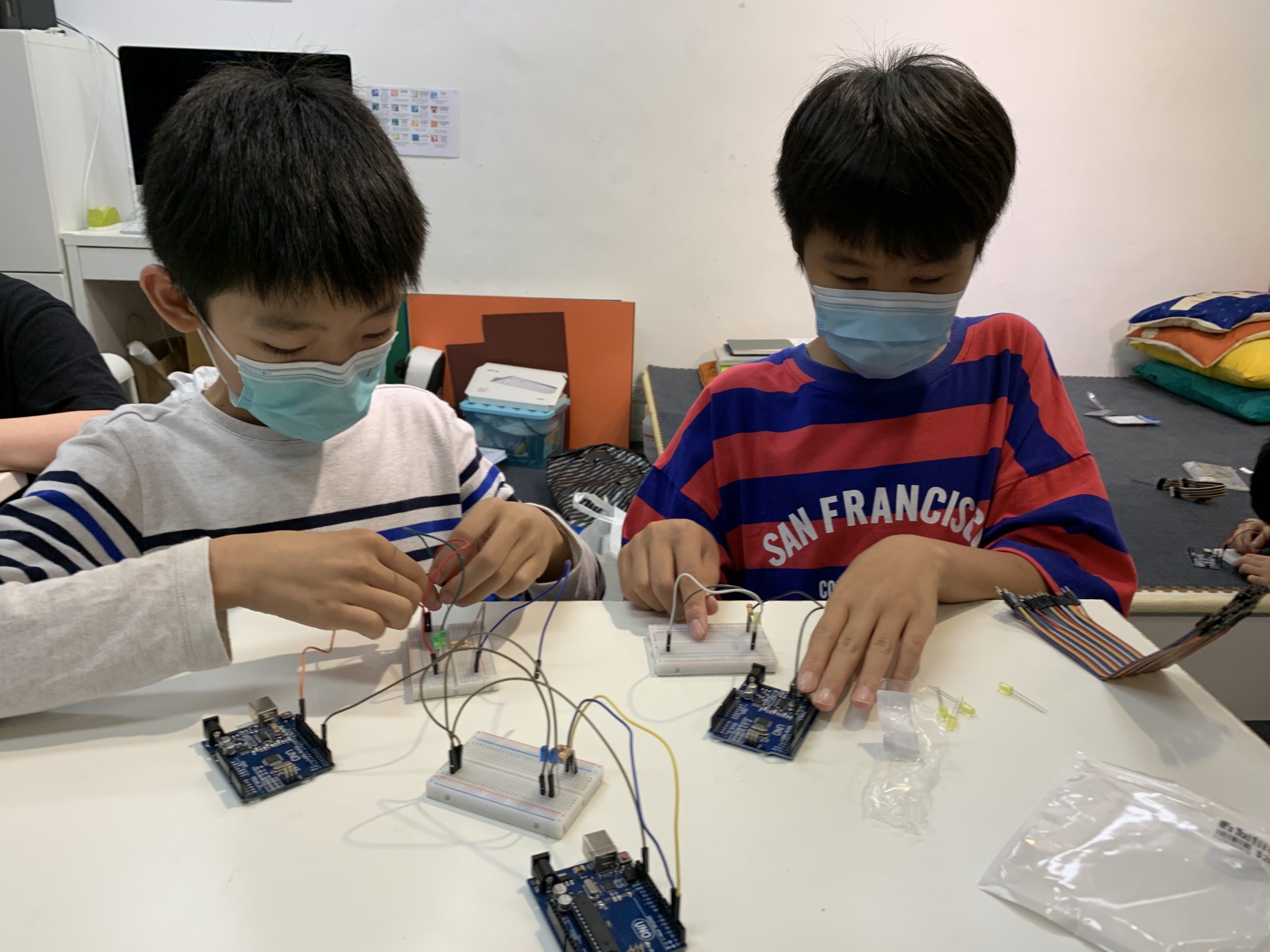
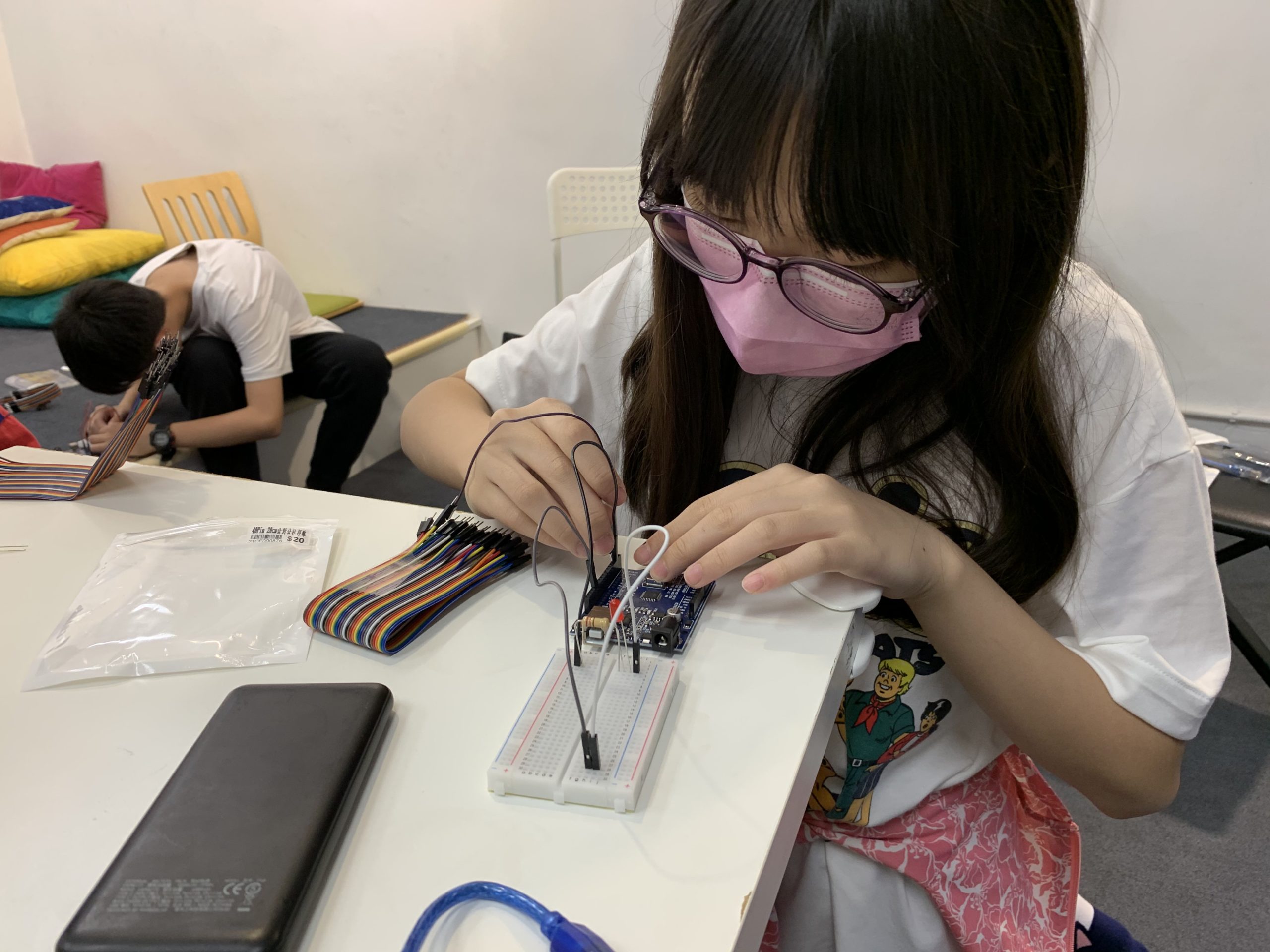
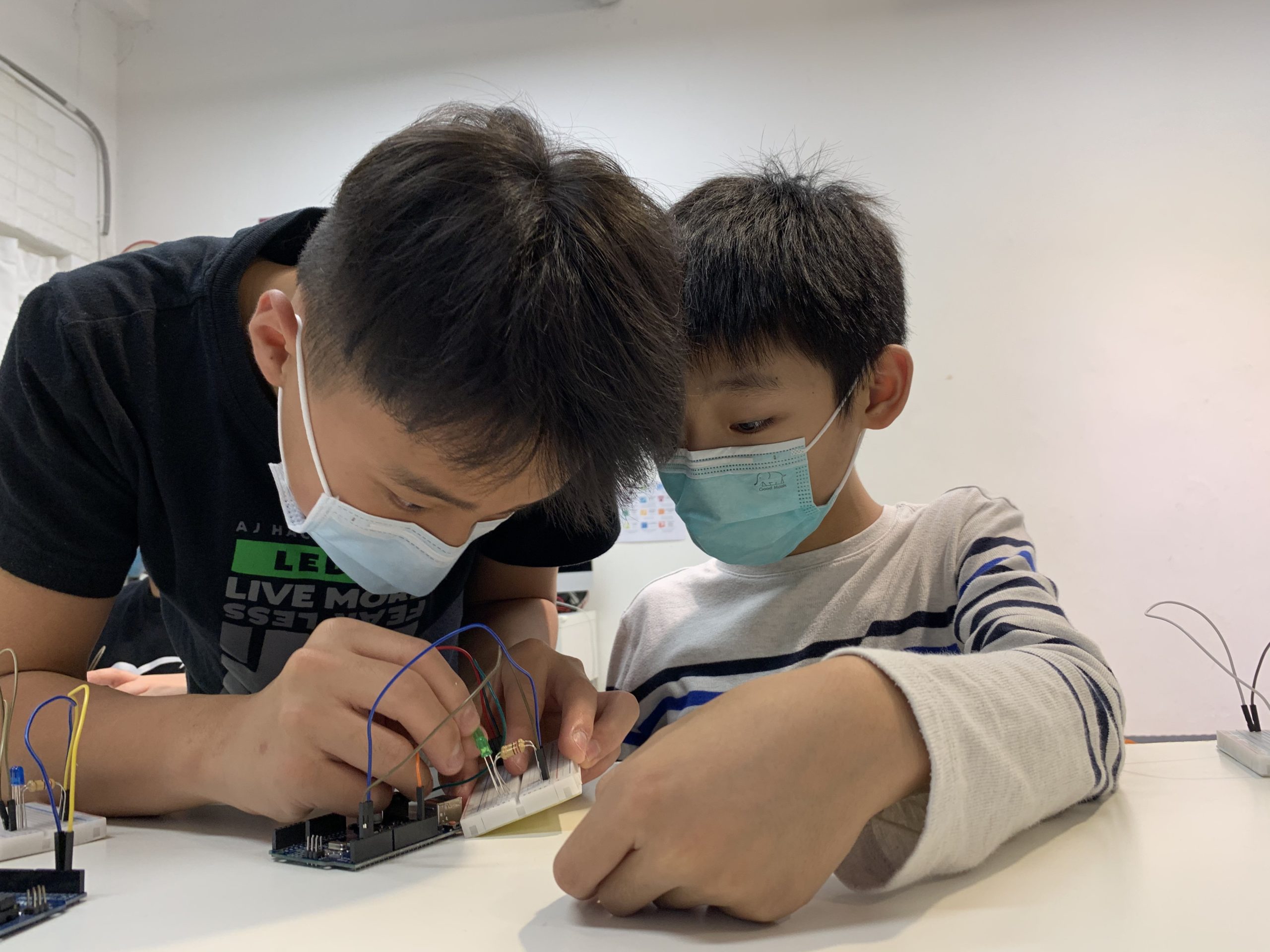
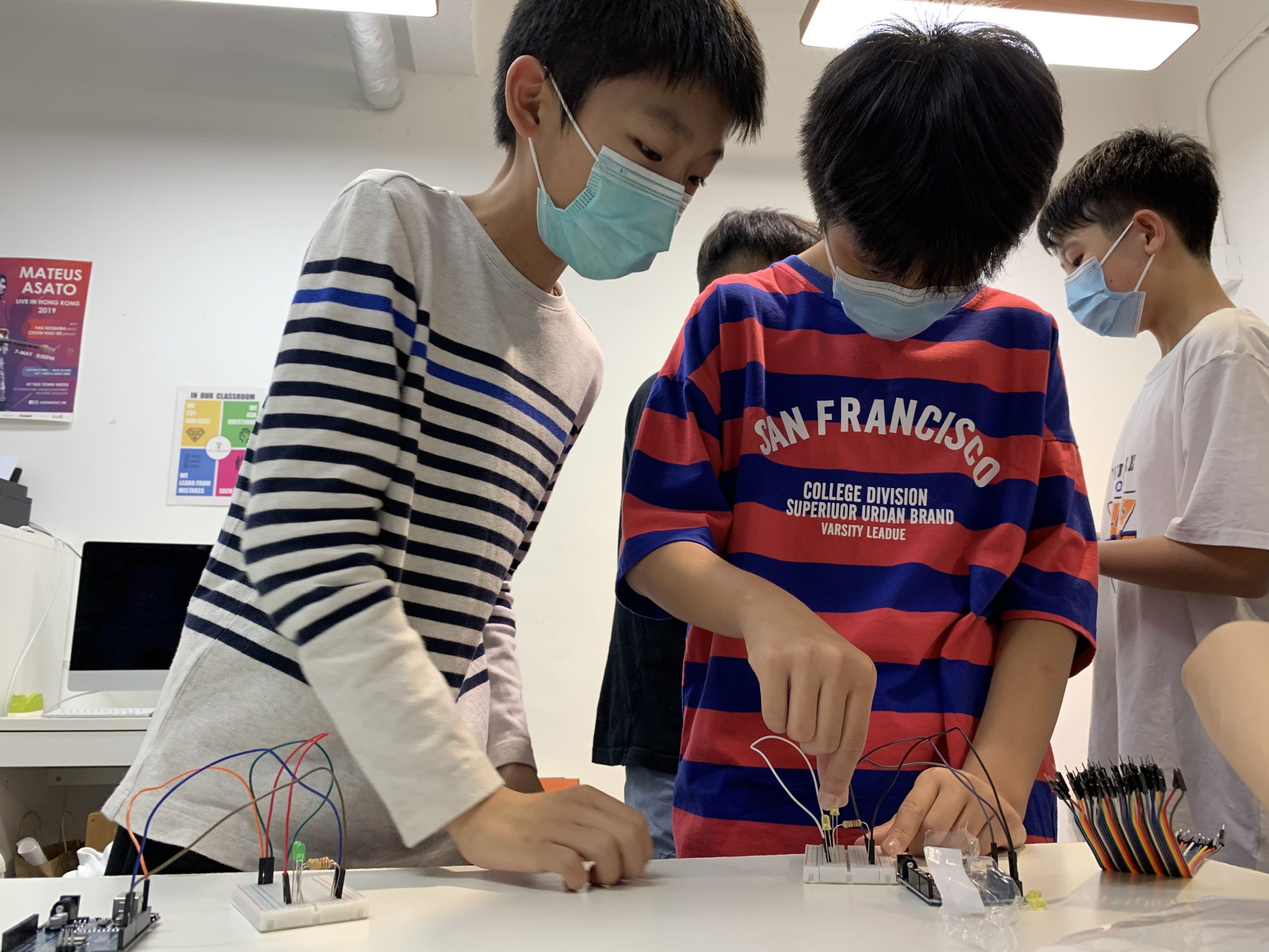
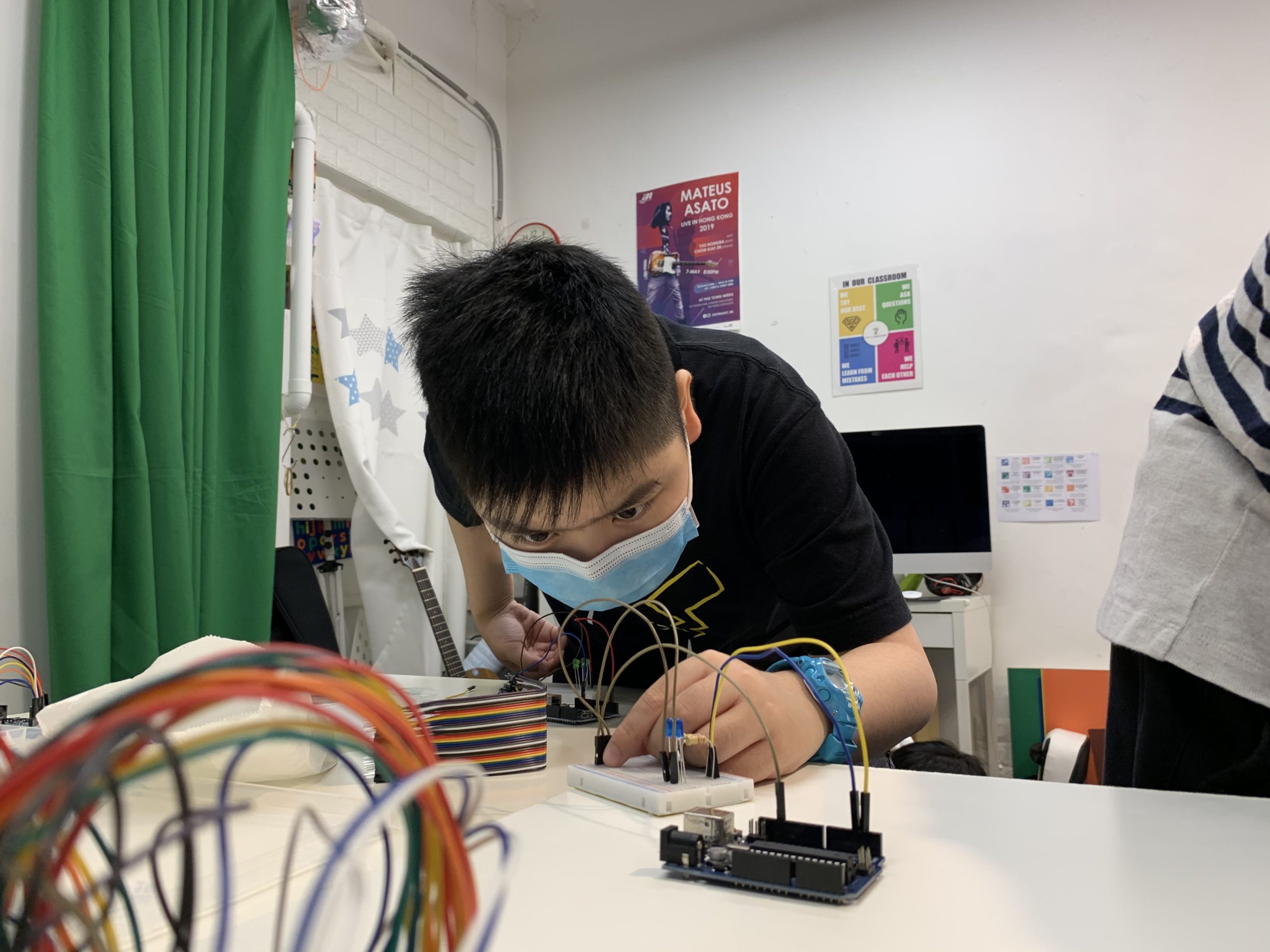
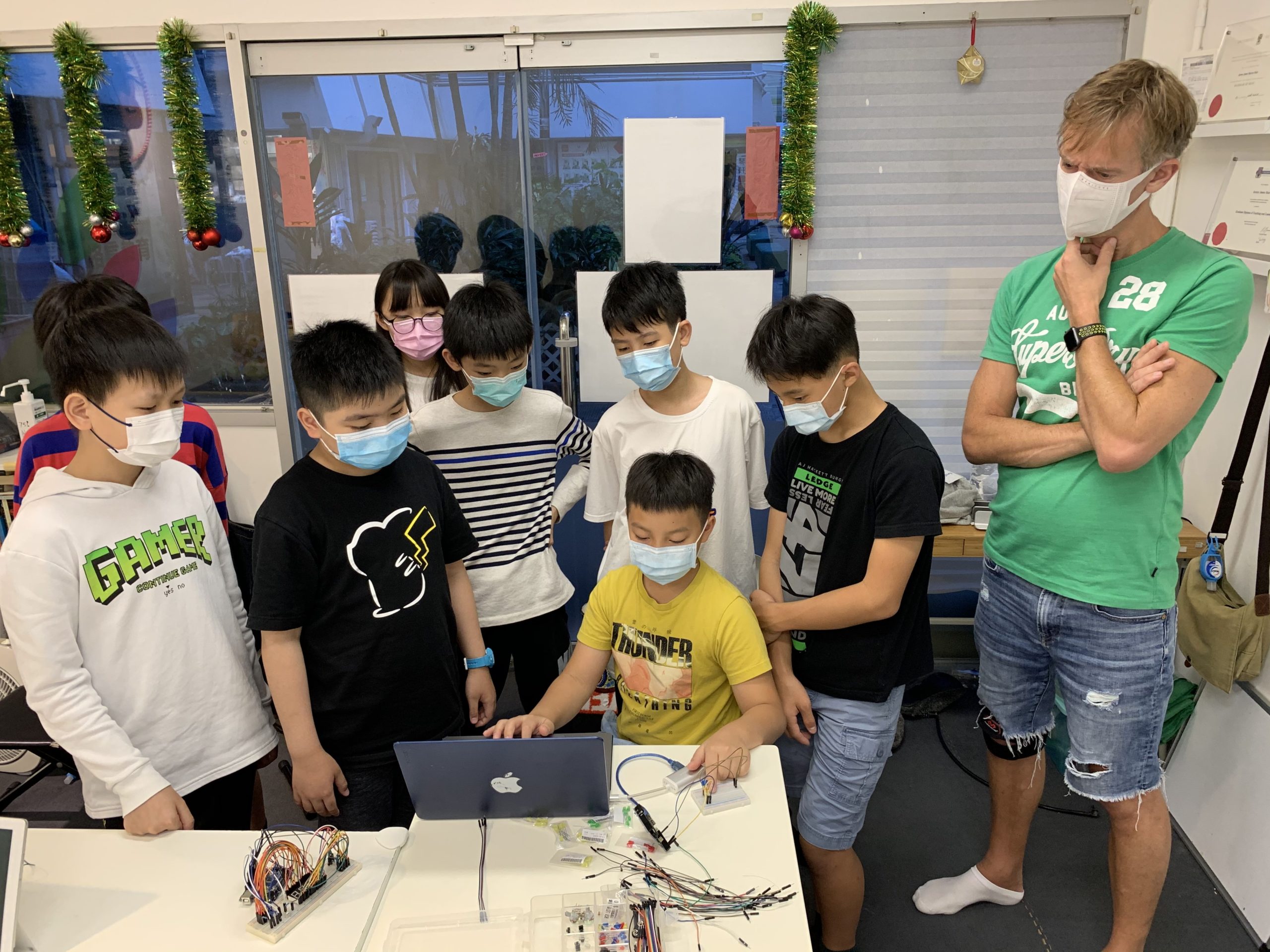
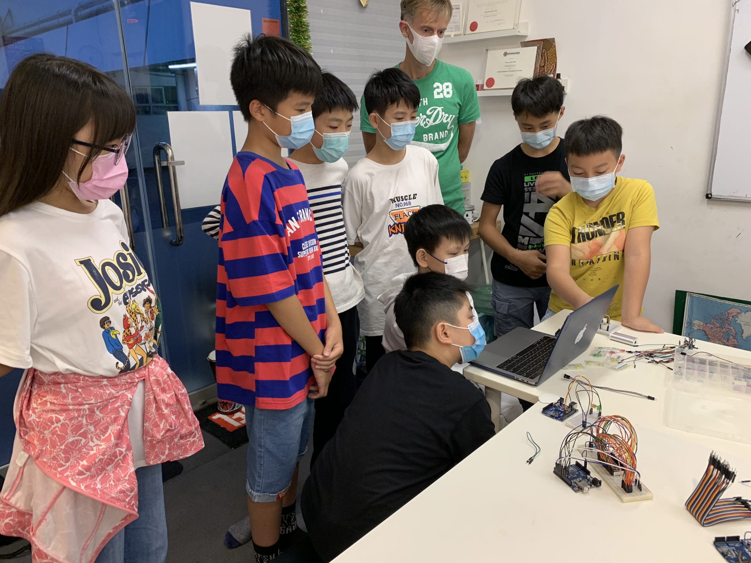
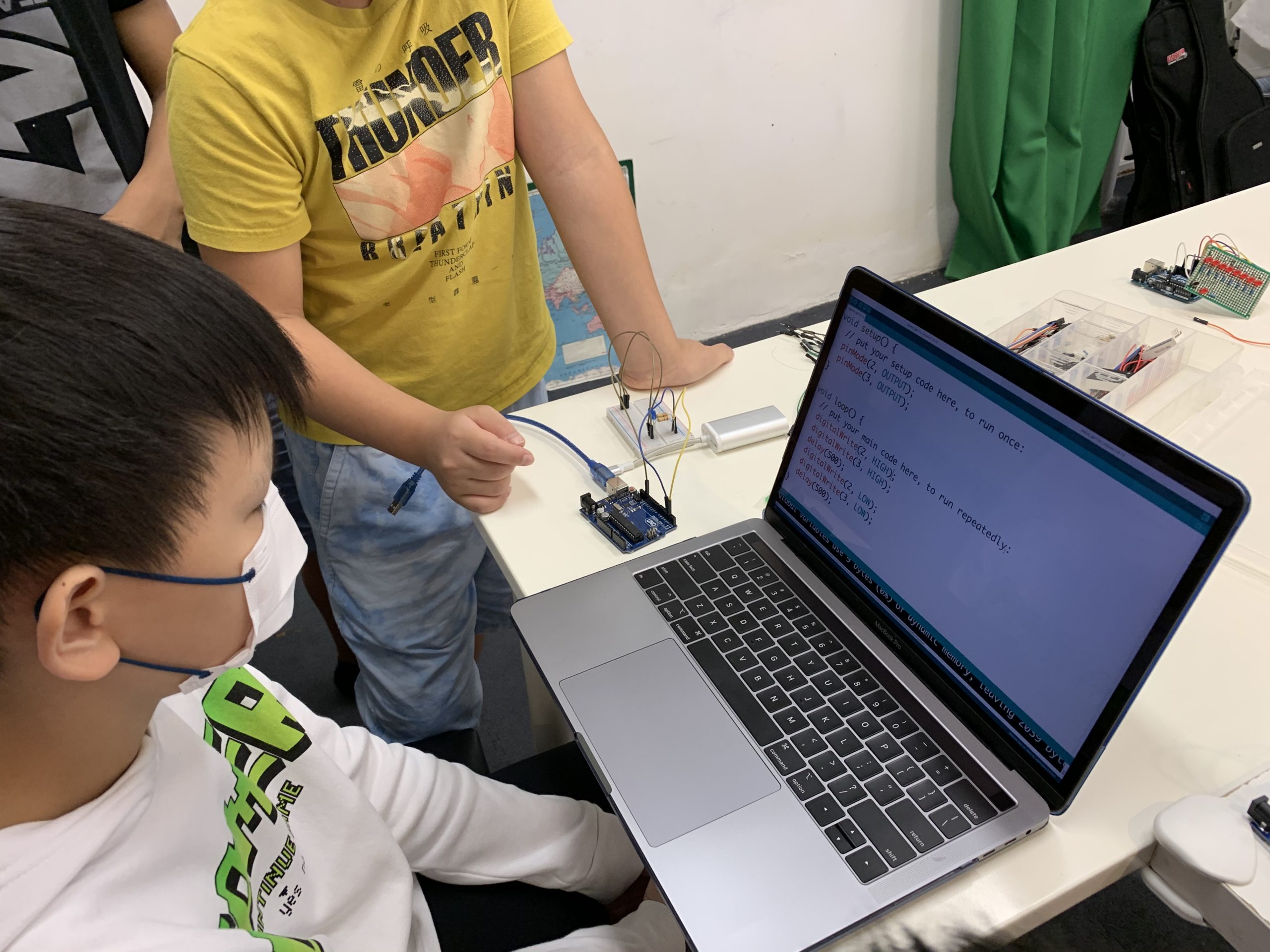
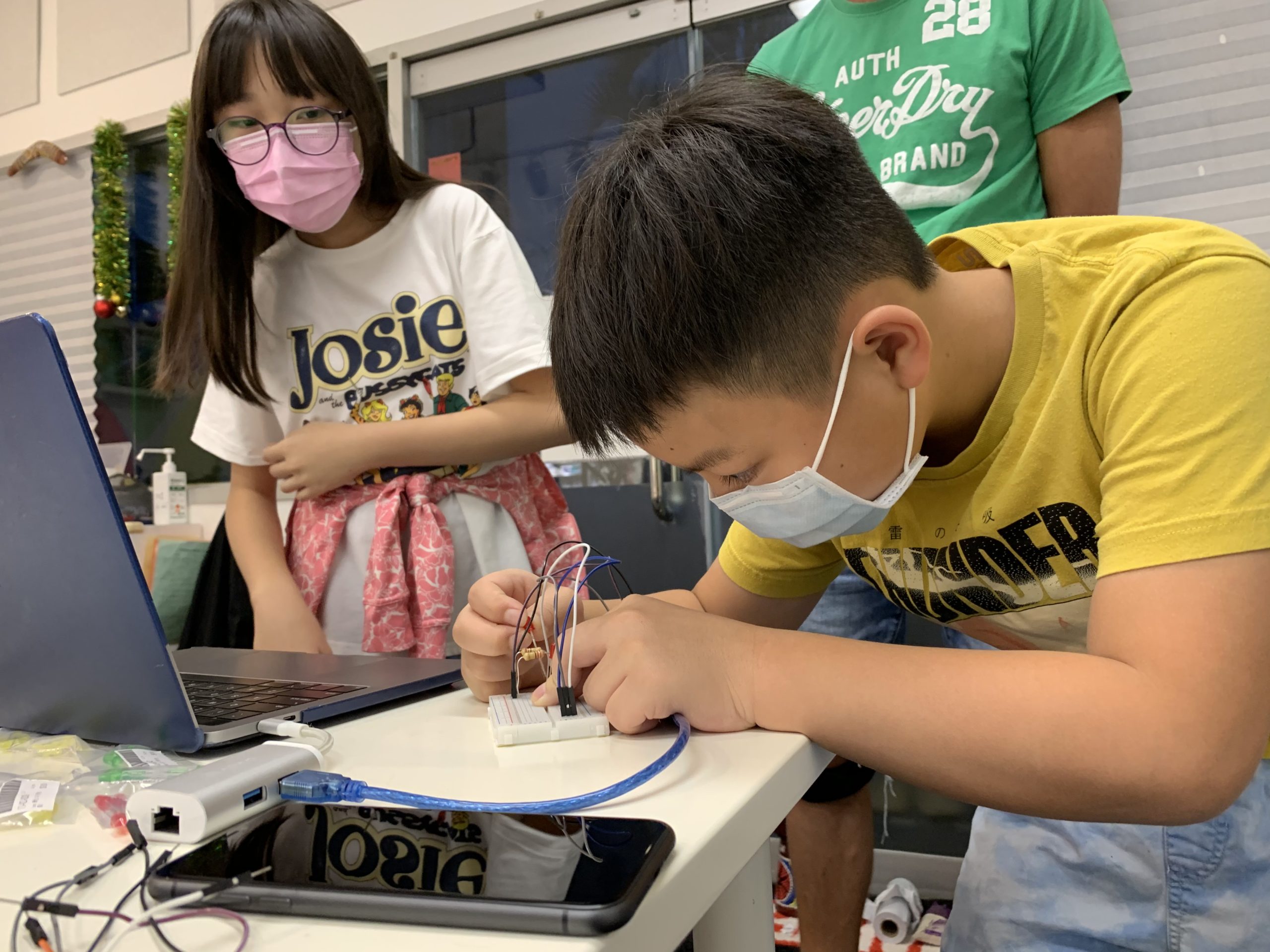
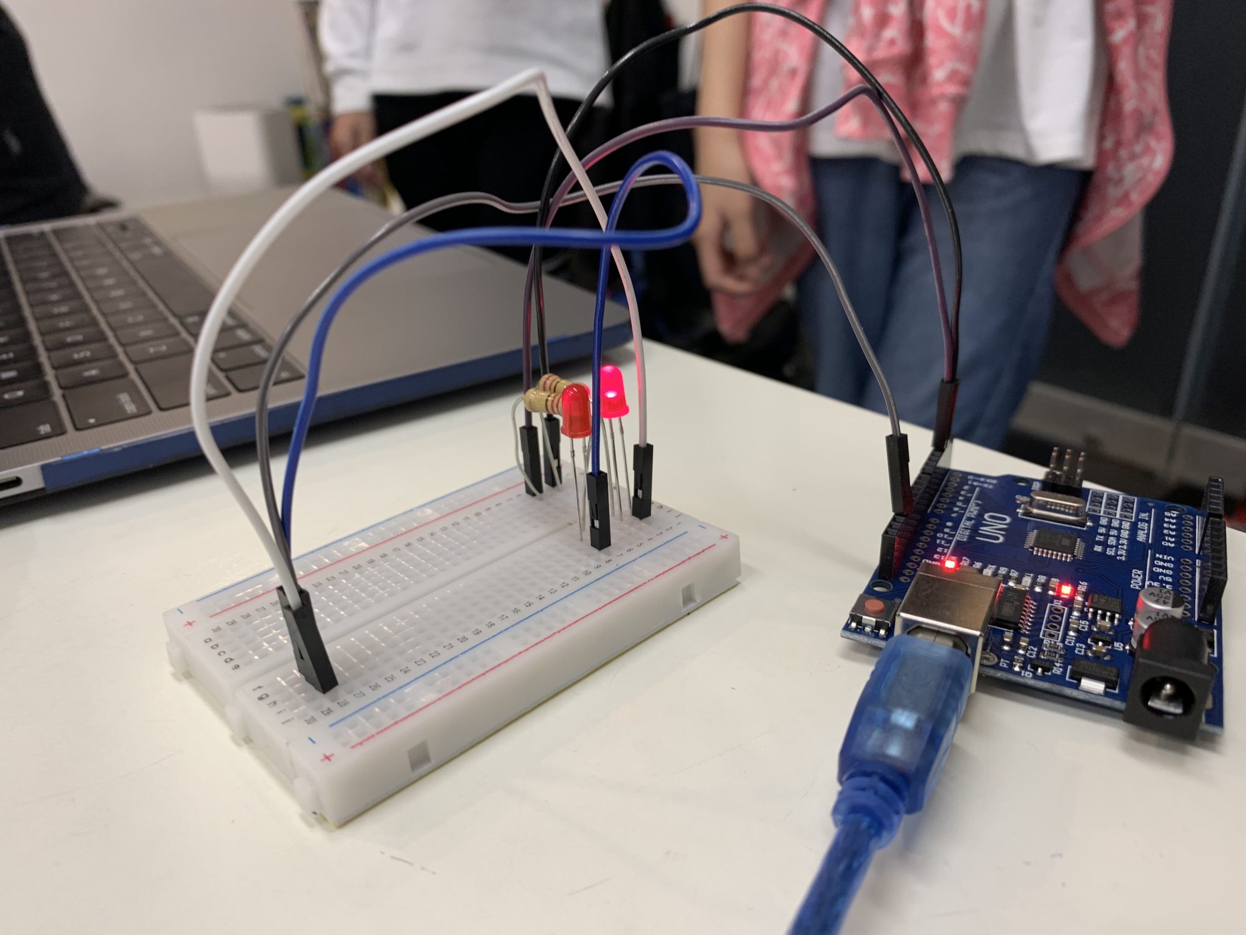
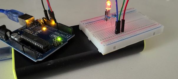
We were so excited that we finished our first volunteer teaching class in our community, shared with a group of 6 kids aged 11 – 12. Introduced them to the world of Arduino by making simple LED circuity.
I feel like I have learned a lot while teaching the students, I have learned how to teach people clearly and how to make them understand how to write the program and create the circuit. This lesson also proved that I can teach people programming and circuitry. I think I can have a better time management skill the next time I teach the kids. I want to have better time management skill because we didn’t have enough time to make other light patterns. – Alex
I have learnt a lot from this teaching experience. My programming skills may not be as good as Alex, but I was a good supporter. When Alex is teaching the class, I guided Alex to bring up different topics to make his teaching more fascinating. I also guided the students to have a better understanding of the program. From this teaching lesson, I have learnt that being a good supporter can help make big difference in how the students think and how the teacher speak. Because I forgot most of the programming techniques, so I took this lesson for granted and I managed to recover most of the techniques. Without this lesson, I don’t think I would even remember how to turn on a led. For this time’s lesson, I am very satisfied in the result, so I would like to continue teaching the kids or other kids! – Mountain
Since ev3dev is Linux based, when PS4 controller connected to the EV3 Brick via Bluetooth, we can identify the handler from a directory call /dev/input. As shown below, event2, event3 and event4 are created when the PS4 controller is connected.
When we looked into the device detail from /proc/bus/input/devices, we can get the following details,
We are going to use the Wireless Controller to control the Dog, event4 is the target handler to get all inputs information. Based on the information we reviewed, we learnt that event4 contains 16 bytes of data as shown below,
tv_sec (long unsigned value) : Time in seconds since epoch at which event occurred.
tv_usec (long unsigned value) : Microsecond portion of the timestamp.
ev_type (unsigned short) : Event type
code (unsigned short) : Event code
value (signed long) : Event value
We are using ev_type, code and value to monitor the PS4 controller inputs. It updates real time for any status change, such as button press, button release, joystick movement. Keep in mind, if a button is being held, it will generate a value ‘1’ for once but no additional update until the button is released, then a value ‘0’ will be generated.
[This part was created by Adam]
PS4 Controller mapping with EV3DEV
# Open the PS4 Controller file at /dev/input/event4 in binary mode
infile_path = "/dev/input/event4"
in_file = open(infile_path, "rb")

# Format of the event contains - unsigned long int, unsigned long int,
# unsigned short, unsigned short, signed int, i.e. LLHHi
FORMAT = 'LLHHi'
EVENT_SIZE = struct.calcsize(FORMAT)
.
.
.
# Read from the file and unpack into five variable based on the format
event = in_file.read(EVENT_SIZE)
(tv_sec, tv_usec, ev_type, code, value) = struct.unpack(FORMAT, event)
This part is to open the file event4 to import the PS4 Controller values into 5 variables based on the predefined format – ‘LLHHi’. We use ev_type, code and value to identify the action from PS4 Controller.
ev_type : There are two main type, type 1 = buttons, type 3 = joystick, dpad and analog trigger
code : Which button or joystick being pressed / moved
value : The action done, button pressed = 1, released = 0, or analog value from joystick and analog trigger
So, we wrote a small program to identify each codes and values from the PS4 Controller. The result is shown below,
Key mapping as shown below

Type = 1, code & possible value

L1 - 310 (0,1)
L2 - 312 (0,1)
L3 - 317 (0,1)
R1 - 311 (0,1)
R2 - 313 (0,1)
R3 - 318 (0,1)
Triangle - 307 (0,1)
Square - 308 (0,1)
Cross - 304 (0,1)
Circle - 305 (0,1)
Share - 314 (0,1)
Option - 315 (0,1)
PS - 316 (0,1)

Type = 3, code & possible value

Left Stick Y - 1 (Up 0 - Down 255)
Left Stick X - 0 (Left 0 - Right 255)
Right Stick Y - 4 (Up 0 - Down 255)
Right Stick X - 3 (Left 0 - Right 255)
L2 - 2 (0 - 255)
R2 - 5 (0 - 255)
dpad Up & Down - 17 (-1, 0, 1)
dpad Left & Right- 16 (-1, 0, 1)
How does the program work
def PS4_Controller():
    global pressed
    global trigger_dog
    global speed
    global speed_backwards
    global speed_forwards
    global turning
    global out

    while True:
        # Read from the file and unpack into five variable based on the format
        event = in_file.read(EVENT_SIZE)
        (tv_sec, tv_usec, ev_type, code, value) = struct.unpack(FORMAT, event)

        if ev_type == 1 and code == 311 and value == 1:
            trigger_dog =  45
            out = 1
        if ev_type == 1 and code == 311 and value == 0:
            trigger_dog = 0
            out = 0

        if ev_type == 1 and code == 310 and value == 1 and out == 0:
            trigger_dog =  35

        if ev_type == 1 and code == 310 and value == 0 and out == 0:
            trigger_dog =  0

        if ev_type == 1 and code == 305 and value == 1:
            pressed = True

        if ev_type == 1 and code == 305 and value == 0:
            pressed = False

        if ev_type == 3 and code == 5:
            speed_forwards = value * 6

        elif ev_type == 3 and code == 2:
            speed_backwards = value * -6

        if ev_type == 3 and code == 0:
            turning = (value*360-(180*255))/255

PS4_Controller_Thread = threading.Thread(target = PS4_Controller)
PS4_Controller_Thread.setDaemon = True
PS4_Controller_Thread.start()

bite = 0
while True:

    speed = speed_forwards + speed_backwards
    print(speed)
    combo(pressed)
    forward(speed,turning)
    bite = Dog_bite(trigger_dog, bite)

in_file.close()
Basic Idea
Since we didn’t want to change the program of ‘the Dog’, we replaced the LEGO Controller part, i.e. receiving LEGO Controller result, with a new function to detect the action from the PS4 Controller buttons and joysticks. When corresponding action done on the PS4 Controller, the function will update the variable for ‘the Dog’ to action.
For example, when we press the circle, the function will detect a value of ev_type = 1 , code = 305 and value = 1. Then, it changes the variable ‘Pressed ‘ to True so that ‘the Dog’ will do combo. If we keep pressing the button, the variable ‘Pressed’ will stay True until we released the button.
Parallel Processing
We made the function parallel processing because it can detect all the status changes from the PS4 Controller. If we use normal function, the function will only read the latest actions from the controller that may result missing some of the actions. Especially, if we want to detect button pressed or released.
Global Variable
When we use global variable, the variable change by the parallel progressing function can be read by the program outside. For the PS4_Controller function detects any actions from the controller, it will change the corresponding variable for ‘the Dog’ to respond, just like the LEGO Controller sending message to ‘the Dog’.
Build instruction and the program
We created the program from scratch without referring any example, you can download from below.
My dad told us that he wanted a RC car with a professional controller like this… that’s one of his childhood dream.
He was so excited with such professional controller we made…. HOWEVER, we built him this ‘car’… LOL
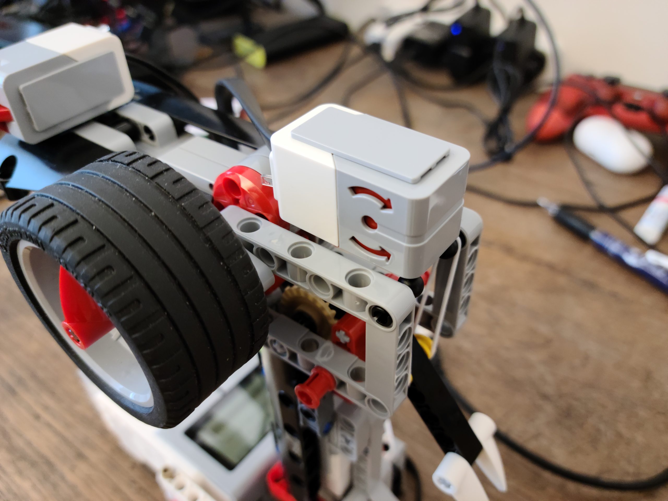
This is a great project to make use of two bricks and the messaging functions, how we connect the remote Controller with the Dog by feeding different data via different ‘mailbox’ is the key.
Features of the remote controller
Turning Wheel
The function of this wheel is to see how many degrees you turn the wheel. The more you turn the wheel, the higher number you get. If you turn it backwards, it will give you a negative number. Thus, positive number is turning right, negative number is turning left.
Direction Sensor
This is the Direction Sensor, this sensor detects how much you have tilted the handle. When you tilt the controller more forward, the higher number the sensor will give. If you tilt the controller backward, it will give you a negative number. Thus, positive number is going front, negative number is going back.
Calibration
The calibration is quite simple. When starts the program of the controller, just need to ensure the turning wheel back to 12’o clock position for easy control. Then, put the controller on a flat table to ensure the controller start from a horizontal position since we will use it’s tilting to control the ‘Dog’ direction.
Once all set, the program will reset the turning wheel angle and the direction sensor back to zero.
These two programs connect two EV3 bricks via Bluetooth. We made different mailboxes to separate the communication between two bricks. For example, if we want to send information or message to tell the Dog how’s Turning Wheel result, it will be using mailbox ‘Turn’. So, we can perform very dedicate communication channels between the Controller and the Dog, make it easy way than using just one mailbox.
Messaging Synchronization
The Controller
# Sychronize the mail box between the robot and the remote
# Ensure the robot get new mail from the remote before start
# Once the robot get the new mail, will confirm Ready and OK to start
i = 0
while mbox.read() != 'Ready':
    trigger_mbox.send(i)
    turn_mbox.send(i)
    combo_mbox.send(i)
    speed_mbox.send(i)
    i = not i
combo_mbox.send(False)
mbox.send('OK')
The Dog
# Sychronize the mail box between the robot and the remote
# Ensure the robot get new mail from the remote before start
# Once the robot get the new mail, will confirm Ready and OK to start
trigger_mbox.wait_new()
turn_mbox.wait_new()
combo_mbox.wait_new()
speed_mbox.wait_new()
mbox.send('Ready')
mbox.wait()
Since we cannot ensure two bricks starting at the same time and same speed, we did a synchronization process to confirm two bricks ‘hand shake’ prior to start. We make the Dog mailboxes to read new mails only, it will wait until the Controller sends a new message to every mailboxes. Once new mails received, the Dog confirm ‘Ready’ and the Controller will reply by ‘OK’. Then, start the process.
It’s important. If the Dog runs faster, a ‘NONE’ message will be read because the Controller have not sent any messages yet. ‘NONE’ is not an value to be processed, which will induce an error.
We set ‘combo_mbox.send(False)’ because we don’t know the last message sent from the Controller is ‘1’ or ‘0’. If we don’t add this, it will result as a glitch that the Dog will randomly do Combo at start.
The Controller
while True:
    if mbox.read() == 'OK':

        combo_mbox.send(combo_sensor.pressed())
        turn_mbox.send(turn_sensor.angle())
        speed_mbox.send(speed_sensor.angle())
        trigger_mbox.send(trigger_sensor.angle())
The Dog
while True:
    # Stop the remote sending new data which will induce overflow
    # If wait time too short, it will be always 'Wait' or send
    # duplicate result
    mbox.send('OK')
    wait(30)
    mbox.send('Wait')

    pressed = combo_mbox.read()
    combo(pressed)

    turning = turn_mbox.read()
    speed = speed_mbox.read()
    forward(speed * 12, turning)

    trigger_dog = trigger_mbox.read()
    bite = Dog_bite(trigger_dog, bite)
In the most beginning we setup the program, we had the Controller keep sending the reading to the Dog. However, it would result as errors because too much information fed to the Dog. So, we also added a ‘hand shake’ process to ensure the Controller to send the reading once the Dog is ready.
Direction Control
def forward(speed, turn_angle):

    # When turn sensor between -40 to 40, go straight
    # Turn right in scale between 40 to 140
    # Turn left in scale between -40 to -140
    # Self rotate to right between 140 to 220
    # Self rotate to left between -140 to -220
    # If the user turn over the limit 220 or -220, the robot will stop
    right_speed_alternator = 1
    left_speed_alternator = 1

    if turn_angle < 40 and turn_angle > -40:
        left_speed_alternator = 1
        right_speed_alternator = 1

    elif turn_angle > 40 and turn_angle < 140:
        right_speed_alternator = 1 - (turn_angle - 40)/100*0.8

    elif turn_angle < -40 and turn_angle > -140:
        left_speed_alternator = 1 - (turn_angle + 40)/100*-0.8

    elif turn_angle > 140 and turn_angle < 220:
        right_speed_alternator = -1
        left_speed_alternator = 1

    elif turn_angle < -140 and turn_angle > -220:
        right_speed_alternator = 1
        left_speed_alternator = -1

    elif turn_angle > 220 or turn_angle < -220:
        right_speed_alternator = 0
        left_speed_alternator = 0
        ev3.speaker.beep()

    if speed < 120 and speed > -120 :
        right_wheel.hold()
        left_wheel.hold()
    else:
        right_wheel.run(speed * right_speed_alternator)
        left_wheel.run(speed * left_speed_alternator)
Forward, Backwards & Hold
In this function, we make the robot move according to the gyro sensor angle. How fast the Dog to move is the angle multiply by 12. Thus, the gyro sensor tilts more forward, it moves faster. If it tilts backward, it goes reverse. We made the robot hold when the angle is between -10 to 10 (-120 to 120) .
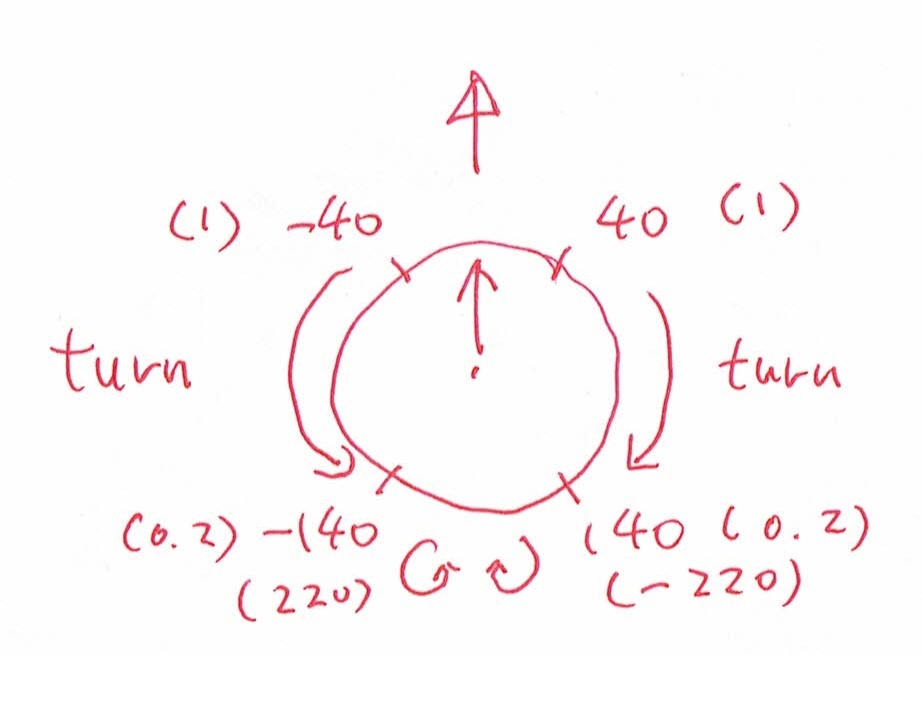
Turning Direction
See above picture, we want the Dog to turn when we rotate the Turning Wheel from the Controller. It will start turning right when Turning Wheel is sitting between 40deg to 140deg or turning left between -40deg to -140deg. We used a formula to calculate how fast we want the robot to turn, the right wheel formula is “right_speed_alternator = 1 – (turn_angle – 40)/100*0.8” and the left wheel formula is “left_speed_alternator = 1 – (turn_angle + 40)/100*-0.8”. So, the more you rotate the Turning Wheel, the bigger of the speed alternator will be resulted. The Dog will turn because we alternate the Dog’s wheels in different speed.
If you turn the wheel over 180 degrees (or -180 degrees), the Dog will stop and beep.
Bite Control
def Dog_bite(angry, bited):
    if angry > 40 and bited == 0:
        forward(0,0)
        ev3.speaker.play_file(SoundFile.DOG_BARK_2)
        head_control.run(1000)
        return 1
    elif angry < 40 and angry > 15 and bited == 0:
        forward(0,0)
        ev3.speaker.play_file(SoundFile.DOG_GROWL)
        return bited
    elif angry < 15 and bited == 1:
        head_control.run(-1000)
        wait(500)
        head_control.run(0)
        return 0
    elif angry > 40 and bited == 1:
        forward(0,0)
        return bited
    else:
        return bited
This function we made the biting part of the dog. If the Controller trigger is held, it will bite. It will growl when the trigger is on the half-way. When we release the trigger, the dog will return to it’s normal form.
Since we don’t want the Dog keep moving when growl or bite. We setup a variable call ‘bited’ to ensure that the Dog will keep in bite position without any movement. Once we release the trigger, the Dog will move again.
Build instruction and the program
We created the program from scratch without referring any example, you can download from below.
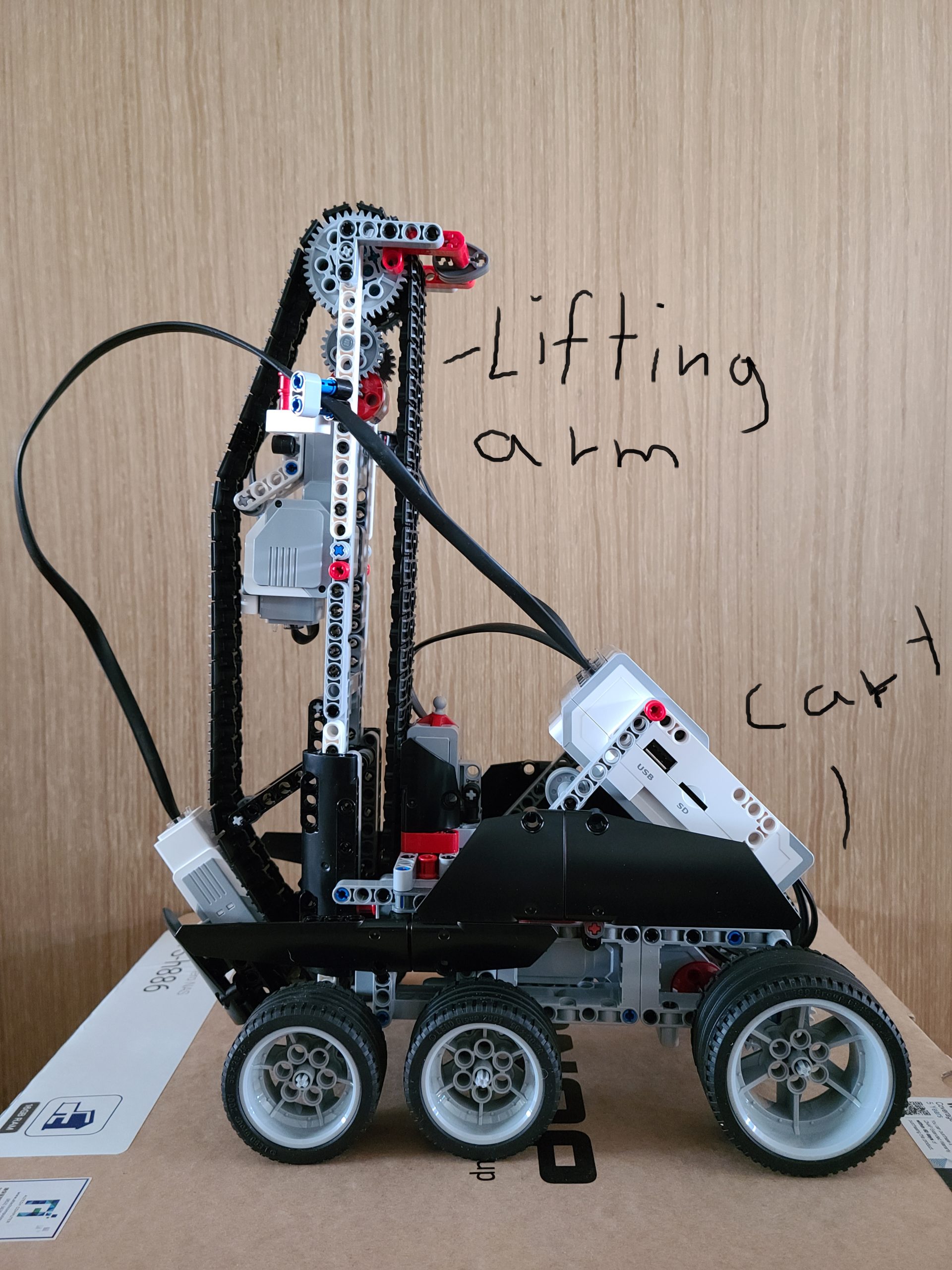
This project is so funny and cool, we are controlling a robot which contain the cart and the lifting arm, so that it can climb stairs. Looks like a Mars rover!!
Features of the robot
Gyro Sensor – It is used to detect or reference the degrees that the project is tilting towards. If the object is tilting forward, then the numbers will be positive, it will be negative if it is tilting backwards. How do we use this gyro sensor in our robot? It can be used to set a limit on how much you should tilt. For example, you want your cart to tilt to -15 then stop and reset degrees counter, then the gyro sensor will come in handy because it detects how much the robot tilts.
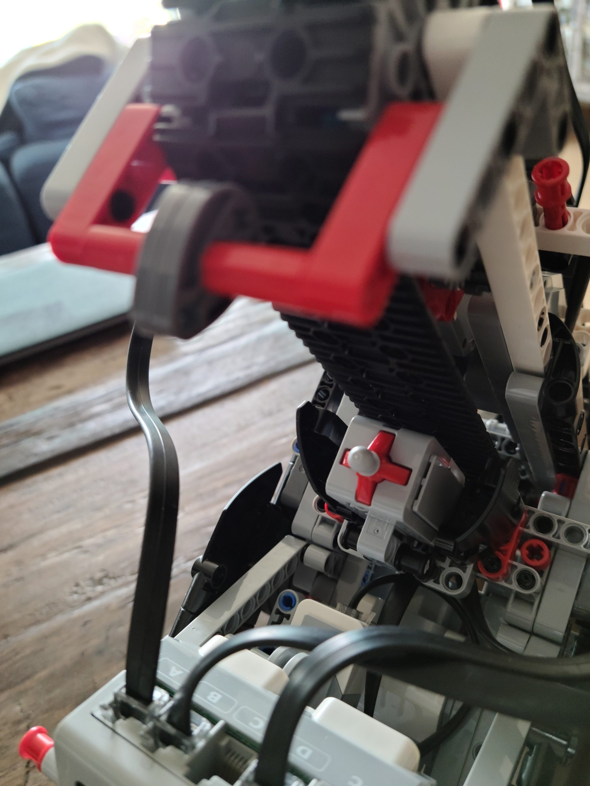
Touch sensor – It is used to send signals when something goes in contact with it. In this stair climbing project, the touch sensor is used as a calibration. When the top part come in contact with the touch sensor, then it will reset the degrees counter and it will return to the straight form. Why is the calibration important? The calibration is used to limit how much the belt should go. If the belt goes over the limit, then the motor will malfunction or in worst scenario, even break the motor.
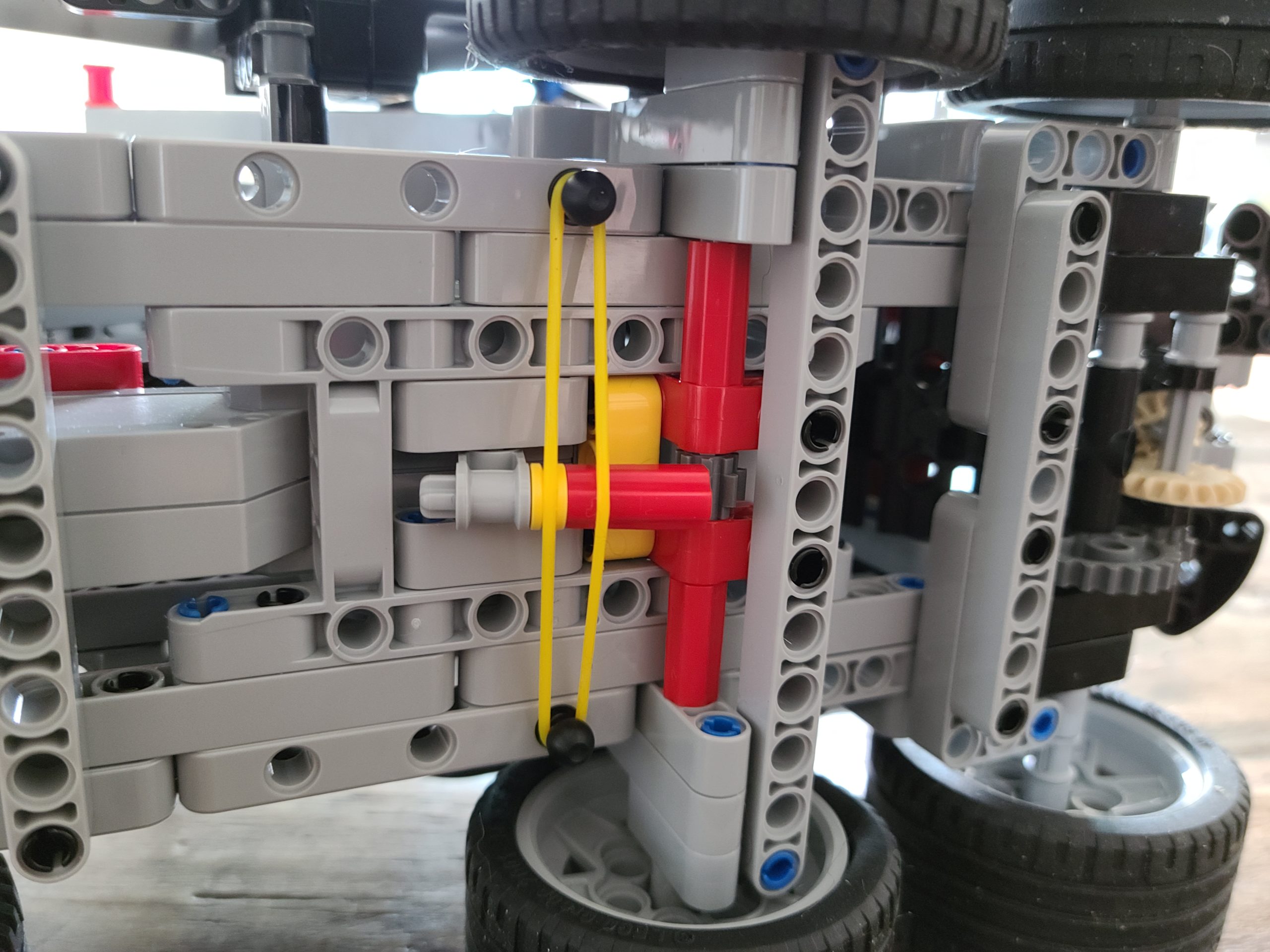
‘Little Fella’ – This little guy’s function is kind of confusing, I thought it was just a noise maker at first. This little guy’s function was unknown until we tested the project. When we tried our first run, we realize that the little guy has the function to stop the middle wheel from moving backwards. What a powerful little fella…
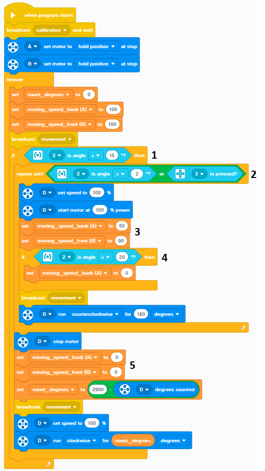
Calibration
This program is the calibration part. It is the most important part of the whole program, because we always need to check the limit and identify the zero point, so that it will not mess up the motor movement because of wrong degree number.
Moreover, we also identify the gyro sensor horizontal level and rest to zero when it sitting on the floor.
So what I did in this program is that I made the lifting arm go up until it presses the button, when it presses the button it will reset the degrees counted so that the top will be the zero point, then the lifting arm goes down by moving the motor clockwise by 2900 degrees. (we got it manually) then we reset the Gyro sensor since it is horizontal to the floor.
Stair Climber Movement concept
When the stair climber moves forward and hit the wall, the front wheel will make the cart going upward and result as tiling up. Once we detect tiling for a certain degree, we will activate the lifting arm to push the cart upwards until it reach the top of stair, we call this landing. Once the cart landed, it will be no longer tilting upward, i.e. no tilting or very small tilting. Then, we will collect the lifting arm to the top of stair and moving forward for the next climbing.
IMPORTANT! When we doing above action, we need to control the back wheel action carefully. If back wheel pushing too much, the cart will flip over because of the center of gravity changed.
How’s the program working?
Check whether the gyro sensor detects tiling and if it is more than 15 degree, i.e. the forward wheel rotate against the wall and the head tilt up. If yes, it will start the lifting action 2.
Determine if the cart landed or the lifting arm reach the max. Otherwise, keep the arm lifting action.
We need to balance the speed of the wheels. If we make the back wheel too fast, the cart will flip over while going up the stairs. If the back wheel goes too slow, the cart will be too slow for the landing and it will be stuck at the edge of the stairs. We also need to make the front wheel rotating speed synchronized to the lifting arm speed.
We have to balance the cart if it is tilting so much like it is going to fall. We have to stop the back wheel so that the cart will not keep moving forward, i.e. change the center of gravity. So, we stop the back wheel for a certain tilting angle that the cart may flip over.
We need to stop the wheels before the lifting arm move up or else the lifting arm is going to snap. After stopping the wheels, we pull the lifting arm back up to the original place. Then, the stair climber keep going for next stair.
Build instruction and the program
We created the program from scratch without referring any example, you can download from below.
The best part for this elephant is installed two sensors to detect the trunk and the head movement, so that we can program this to avoid the motor over-driving the head and trunk to induce unnecessary damaged. Calibration is very important for machine and robot, identify the zero (or required) position, so that they can be working within the expected range and accuracy. The calibration will run every time when the elephant start because we got unknown starting position of the head and trunk. Once, it dance, it will be always the same.
As you can see above, there are two sensors installed – color sensor and touch sensor.
During the head is moving up, the color sensor is detecting the color in it’s front. When the elephant raises it’s head up to the limit, a red color should be detected. So, we did the coding as below.
When we setup a robot, we actually need to do some manual work to understanding your robot. Prior we wrote this calibration program, we analysis the movement of the head to understand the moving direction and the stroke of the head, keep those as preset ‘parameter’ – we got ‘head (D) down’ is ‘-800’.
Then, we start the program in a loop by detecting the color sensor until it detect ‘red’. Before the red color being detect, the motor controlling the head keep moving up for every 10 degree, so that the head will not be crushed.
Once red color detected, the movement will stop and the motor degree count reset to the ‘zero’ position, so that we can control the elephant with a range of 0 to -800.
Same as what we done for the head calibration, we also need to do some manual work to understand the moving direction and the stroke of the trunk, we got ‘trunk (B) down’ is ‘900’.
Using exactly the same coding for the calibration but change the detective sensor from color sensor to touch sensor because touch sensor was installed when the trunk move up and it will hit the touch sensor.
Again, once the touch sensor is touched, stop the raising trunk and reset the degrees count, set this as ‘zero’ position.
Build instruction and the program
We created the program from scratch without referring any example, you can download from below.
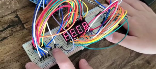
This 4 digit counter was built with 4 7-segment LED display and it can support both common anode and common cathode circuity
This is our second Arduino project, using 4 piece 7-segment LED display to create a DEC / HEX counter which can support both common anode and common cathode components.
7 Segment Display
See the photo for how we connect the 7 segment display, you need to connect a – g & DP to the corresponding pin in the Arduino board to turn each them on & off. Then, you need to connect the common to the GND or 5V+, which depends on which type of diode you are using, i.e. Common Anode or Common Cathode. The one we are suing in this project is common cathode. But, we don’t connect this to ground, we will explain later.
SO, if you want to display a number of 5, what you need to do is..
Common = GND, a = 1, b = 0, c = 1, d = 1, e = 0, f = 1, g = 0
How to connect four displays separately?
Since we were making a 4 digits counter with four separated display, we need to control total 7 x 4 ports without the DP as well as a switch for doing inputs, it’s 29 ports. However, our Arduino only can support 13 ports. How can we control all of them?
We use the common cathode (GND) as the control, any idea? For a common cathode display, it is only working when the common connect to GND or a LOW port. What will happen if we give a HIGH (5v) to common? The answer is, it will not be working no ever what signal generates to a – g & DP port. So, we are using the common as a switch between each single 7 segment display.
You can take a try with one 7 segment display, connect the common to a port instead of GND. Then, see the different for common = high and common = low.
Since we can control 4 displays on & off, we can use 7 ports to generate signal to all four display. Then, switch on the one you want to display. We have now,
Port 2 – 8 connect to a – g for all four displays
Port9 – display one, one place
Port 10 – display two, tenth place
Port 11 – display three, hundredth place
Port 12 – display three, thousandth place
If we want to display ‘5’ in the hundredth place, it will be
Port 2 – 8 = 1, 0, 1, 1, 0, 1, 0
Port 10 = 1
Port 11 = 1
Port 12 = 0
Port 13 = 1
If you keep all the above and change Port 13 = 0, both thousandth and hundredth place will display 5. See?
How can we see different numbers the same time?
Do you know ‘Persistence of vision’? When you see something, the image keep in your eye for a short period of time prior it disappear, normally 1/16 second. If there is the second image come into your eye before the last one disappear, you will see them appear ‘the same’ time, try to flickering your finger quickly and see what happen. So, if you keep displaying something within 1/16 sec, you will see all of them. Got it?
Yes, if we can display all four numbers within 1/16 sec. Your eyes and brain is being cheated to believe that all four numbers are displaying the same time. But actually, what we program is switching display one by one in a very high speed.
Our program features
We made a 4 digits counter with the following features,
It support 7 segment set with common anode or common cathode, but not mix.
It can set how much it count, input the increment need.
Count in decimal from 0 – 9999 or hexadecimal #0 – #FFFF.
Pause the count when switch press.
Keep in mind, I have port 2 – 8 connect to a – g, port 9 for a switch and port 10 – 13 connect to common of displays.
// display a single digit with the specified digit place (0 - 3) and number (0 - 0)

void digit_display(int place, int number){
  int i = 0;
  const int number_count_array[19][7]= {
                   {a,a,a,a,a,a,b},
                   {b,a,a,b,b,b,b},
                   {a,a,b,a,a,b,a},
                   {a,a,a,a,b,b,a},
                   {b,a,a,b,b,a,a},
                   {a,b,a,a,b,a,a},
                   {a,b,a,a,a,a,a},
                   {a,a,a,b,b,b,b},
                   {a,a,a,a,a,a,a},
                   {a,a,a,b,b,a,a},
                   {a,a,a,b,a,a,a},
                   {b,b,a,a,a,a,a},
                   {a,b,b,a,a,a,b},
                   {b,a,a,a,a,b,a},
                   {a,b,b,a,a,a,a},
                   {a,b,b,b,a,a,a},
                   {b,a,a,a,a,b,a},
                   {b,b,a,b,a,a,a},
                   {b,b,b,b,b,b,a}
                                       };
  digitalWrite(led_1,a);
  digitalWrite(led_2,a);
  digitalWrite(led_3,a);
  digitalWrite(led_4,a);
  digitalWrite(led_1+place,b);

  for(i=0;i<=6;i++){
    digitalWrite(start_pin+i,number_count_array[number][i]);
  }
  for(i=0;i<=6;i++){
    digitalWrite(start_pin+i,b);
  }
}
We defined 0 – F including three special character h, d & ‘-‘ into an array – number_count_array[], using a & b instead of 1 & 0 because we wrote this program to support both common anode and common cathode display. If the display is common anode, will define a = 0 & b = 1. Otherwise, it will be a = 1 & b = 0 for common cathode. When the function being called, we need to provide digit place and number to be display, i.e. digit_display(0,5), will display 5 at 1st display, i.e. one place. Once the number is displayed, it need to be erased prior exit the function.
4 digits number display
// display a 4 digits number and how long for the display stay, i.e delay target, 100 = 0.1s, 1 = 0.001s

void four_digit_display(unsigned int number, int delay_target){
  int th; // thousandth place
  int h; // hundredth place
  int t; // tenth place
  int o; // ones place
  int d;

    th = number / pow(number_system,3);
    number -= th*pow(number_system,3);

    h = number / pow(number_system,2);
    number -= h*pow(number_system,2);

    t = number / number_system;
    number -= t*number_system;

    o = number;

    for (d=0; d<=delay_target;d++){
      if (o > 0 or t > 0 or h > 0 or th > 0){
       digit_display(0,o);
      }
      if (t > 0 or h > 0 or th > 0){
        digit_display(1,t);
      }
      if (h > 0 or th > 0){
       digit_display(2,h);
      }
      if (th > 0){
        digit_display(3,th);
      }
      delay(1);
    }
}
We need to tell this function what number to be displayed and how long it stay on the screen, the target number can be 0 – 9999 for decimal system or 0 – 65535 (#0 – #FFFF) for hexadecimal system. Once it get the number, it will identify the individual digit place and it’s number. Then, it will call the digit_display to display the individual number at the digit place one by one. Using a for to achieve the target display time, i.e. the delay_target.
Press button control
// port - the port connect to the switch
// value - the value you want to display when running the function
// return is the uSecond for the button pressed

int press_button(int port,int value,int routine){
  int hold_button = 0;

  while (true){
    if (routine == 9){
      four_digit_display(value, 1);
      while ( digitalRead(port) == HIGH){
        hold_button ++;
        delay(1);
        four_digit_display(value, 1);
        if (digitalRead(port) == LOW){
          return hold_button;
        }
      }
    }

    if (routine != 9){
      digit_display(1,16);
      digit_display(3,17);
      digit_display(routine,18);
      while ( digitalRead(port) == HIGH){
        hold_button ++;
        delay(1);
        digit_display(1,16);
        digit_display(3,17);
        digit_display(routine,18);
        if (digitalRead(port) == LOW){
          return hold_button;
        }
      }
    }
  }
}
That’s the press button function, we need to tell the function which port of the switch to read, what number need to display or routine ‘not 9’ for special function (that’s for DEC/HEX selection, will explain later). Then, it will return the press time, so that we can identify short press or long press that we can achieve ‘select’ and ‘confirm’ with only one button. Since we need to keep the display when waiting for the press button, that’s why we need to send the existing number to this function, it will call the four_digit_display to display the number when counting the press time.
For routine ‘not 9’, it’s actually doing the same thing to count the button press time. However, it is being call when doing DEC & HEX selection, so that the display is ‘h d-‘ instead of existing number.
Input increment
int increment_input(){
  int confirm = false;
  int hold_button;
  int press_target = 100;
  int place_value=0;
  int increment_value = 1;
  int increment = 0;

  while(confirm == false){

    hold_button = press_button(button, increment, 9);
    four_digit_display(increment,1);

     if (hold_button <= press_target && hold_button != 0){
      increment += increment_value;
     }

     if (hold_button > press_target) {
      place_value++;
      increment_value *= number_system;
     }

     if (increment >= number_system*increment_value && place_value < 4) {
      increment -= number_system*increment_value;
     }

     if (place_value == 4){
      return increment;
     }
  }
}
That’s the function to input what will be the increment when counting start from 0. As we mentioned that we will get the press time from press button function, we use short press (<100ms here) to be the number adder and long press as the confirmation. Once the function start, it is waiting for the button press, short press is rotating number from 0 – 9 (DEC) or 0 – F (HEX), i.e. see number_system later. Long press will be confirmation and go for the next place until four digit input, it will return the confirm increment number.
When we call the press button function, we need to provide the existing number to keep the number being display.
Decimal and Hexadecimal selection
int d_h_declare(){
  int change = 0;
  int hold_button;
  int press_target = 100;

  while(true){
      digit_display(1,16);
      digit_display(3,17);
      digit_display(change,18);
      hold_button = press_button(button,0,change);

      if (hold_button <= press_target && hold_button != 0){
          if (change == 0) {
            change = 2;
          }
          else{
            change = 0;
          }
       }

       if (hold_button > press_target) {
          if (change == 0){
            return 10;
          }
          if (change == 2) {
            return 16;
          }
       }
  }
}
A function to select between decimal or hexadecimal, a ‘h d-‘ will be displayed. Short press to select between h(HEX) and d(DEC), ‘h d-‘ or ‘h-d ‘. Long press to confirm. Once confirm, it will return 10 or 16 into the number_system, it is global variable.
Common anode and common cathode
int Common_GND_or_Common_Anode(){
  int hold_button;
  int press_target = 150;

  while(true){
    hold_button = press_button(button,2,9);
    if (hold_button <= press_target && hold_button != 0){
      if (a == 1){
         a = 0;
      }
      else{
        a = 1;
      }
      if (b == 0){
        b = 1;
      }
      else{
        b = 0;
      }
    }
    if (hold_button > press_target) {
       break;
       }
  }
}
We tried to make my program to support both common anode and common cathode display. Since we used common cathode display to build my circuity, common cathode was defined as default. When it start, it will display a ‘2’ if you connect to common cathode display or ‘000 ‘ if you connect to common anode. Use short press to switch between ‘2’ & ‘000 ‘, long press to confirm once ‘2’ is displayed. Then, the program will switch a & b (check back individual number), common anode – a = 0, b = 1, common cathode – a = 1, b = 0.
It will be appreciated if you can share with me idea for how to detect common anode and common cathode automatically.
Let’s start
We have everything be ready but the main counting program… it is easy. Prior you start this, do the setup program in the following steps,
Confirm common anode or common cathode
Which number system you need to count – decimal or hexadecimal
Input the target increment value
Start the counting loop!
Easier Life
Actually, it is much easier to make the circuity by using a 4-in-1 7 Segment display or even some other display module, controller like MAX7219. But, it was really fun for us to start from very basic, making a ‘time bomber’ like counter. Hope you enjoy this project.
Working on the controller like MAX7219 is something new and will be interesting too.
When you deal with diode or transistor components such as LED, 7 Segment display, RGB LED, etc., you need to understand whether the component is common anode or common cathode, it will give you completely different result.
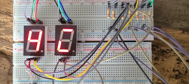
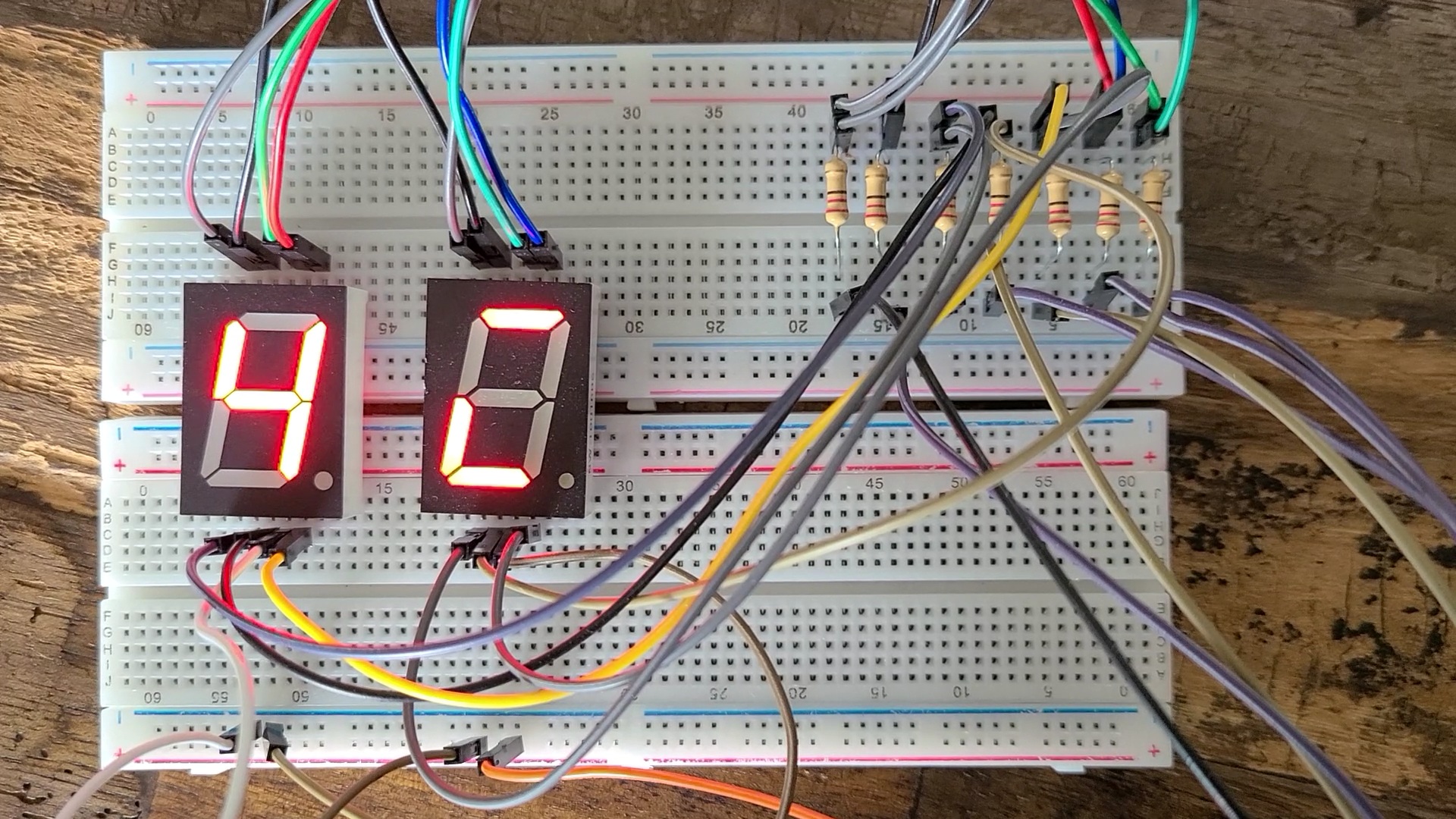
7 Segment Display
Let’s us the 7 Segment display as example.
All a – g & dp are connected to a ‘common’. When the common is common anode, we need to connect this to a high voltage, sometime 5V, so that current will be generated when a – g & dp is LOW. On the other hand, if the common is common ground, we need to connect this to a low voltage, most of the time is ground, so that current will be generated when a – g & dp is HIGH.
Common anode – the segment will be lit if the signal pins a – f & dp is LOW
Common cathode – the segment will be lit if the signal pins a -f & dp is HIGH.
As you can see from the above photos, left display is common cathode and right one is common anode. When we display a number 4 to the common cathode display, it will give the opposite result from the common anode. If you display a number 4 in the common anode device, it will give the same opposite result in common cathode device.
Switching between 1 & 0
So, when you develop the program, you need to understand what device is going to use. Otherwise, you need to do some switching between 1 & 0, just like the program below.
int start_pin = 2;

void setup() {
  // put your setup code here, to run once:
  int p;
  for (p=start_pin; p<start_pin+7; p++){
    pinMode(p, OUTPUT);
  }
}

void loop() {
  // put your main code here, to run repeatedly:
  int i = 0;
  int j = 0;
  int number = 0;
  int d = 0;
  int segment = 0;
  const int number_array[][10]={{1,1,1,1,1,1,0},
                                {0,1,1,0,0,0,0},
                                {1,1,0,1,1,0,1},
                                {1,1,1,1,0,0,1},
                                {0,1,1,0,0,1,1},
                                {1,0,1,1,0,1,1},
                                {1,0,1,1,1,1,1},
                                {1,1,1,0,0,0,0},
                                {1,1,1,1,1,1,1},
                                {1,1,1,0,0,1,1}
                                };

  for (number=0;number<10;number++){
    for (d=0;d<100;d++){
      for (segment=0;segment<8;segment++){
        digitalWrite(start_pin+segment, number_array[number][segment]);
      }
    delay(10);
    }
  }

  for (number=0;number<10;number++){
    for (d=0;d<100;d++){
      for (segment=0;segment<8;segment++){
        digitalWrite(start_pin+segment, not number_array[number][segment]);
      }
    delay(10);
    }
  }
}
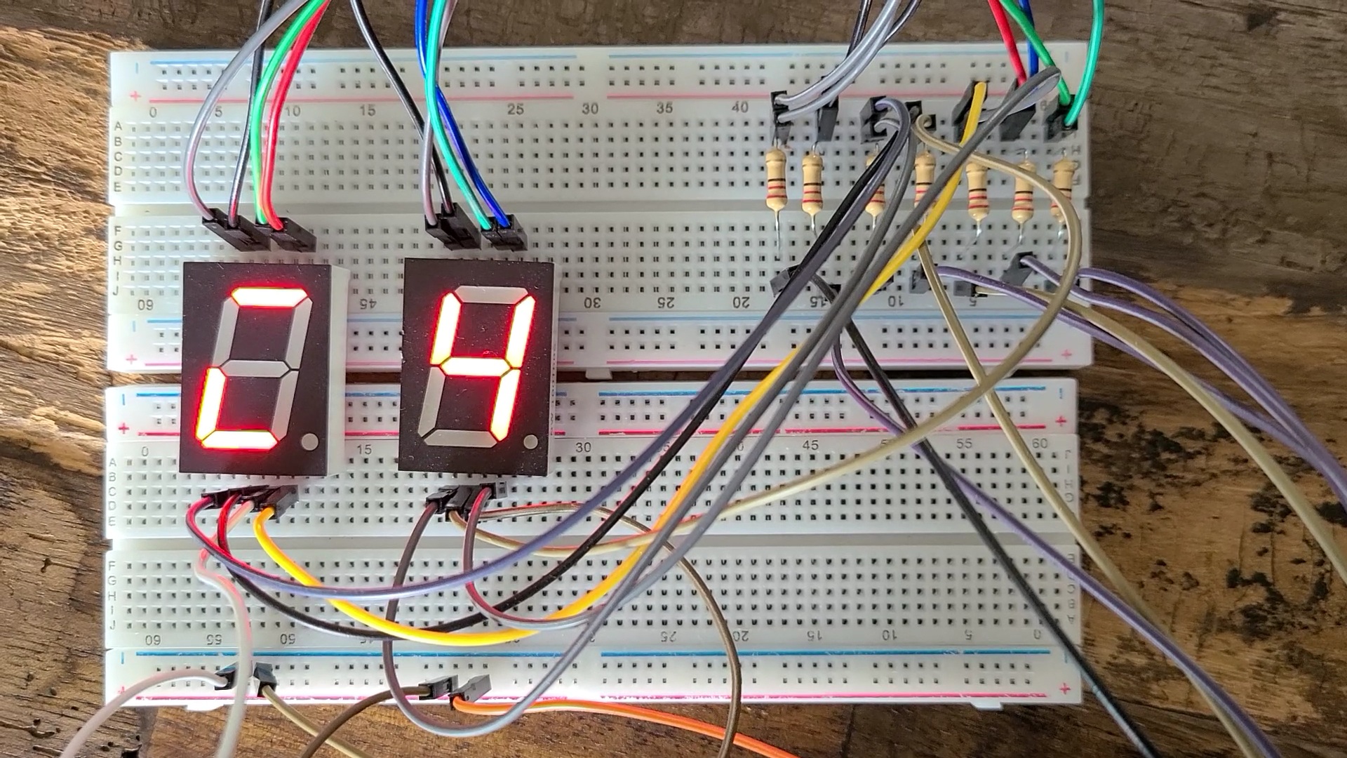
This program is developed with common cathode assumed, the number_array with 1 is on, 0 is off, i.e. 4 is 0110011. When apply the same pattern to the common anode device, it will look like ‘1001100’, the monster you see in those picture.
So, we add a ‘not’ to the line we highlighted in the code, it will give the opposite value to the pin, i.e. 1 -> 0, 0 -> 1. Thus, the data output of 4 will be changed from ‘0110011’ to ‘1001100’, it will be 4 in the common anode but a monster in common cathode.
RGB LED
7 segment is quite easy to hand. But, take a look of RGB LED. I would prefer using common cathode RGB LED, because it is easy for me just follow the color code. But for common anode one, you need to do something like 255 – the color code as shown below, have a try!
R – Red, G – Green, B – Blue, basic display component to display color. We call this as one pixel for all display unit, such as monitor, TV and smart phone. It contains three inputs for red, green and blue, as well as a common ground(1). When we apply ‘analog’ voltage(2) to each corresponding pin, it will display the corresponding scale of the color. For Arduino, it can provide 0-255 scale of ‘analog’ voltage to the pin, i.e. we can get 256 different color scales of red, green or blue. If we put them together, it will give 256x256x256 = 16,777,216 colors!
Since we need to provide ‘analog’ voltage to the RGB LED, we must be using port with ‘analog’ output support that you can see ‘~’ next to the port number, so that you can write 0 – 255 to the port to control color scale to generate different color and achieve different colors combination. Refer to above table for examples of color combination (we call this color code) or the link to a color code web site. All the color is the combination of RGB in term of hexadecimal number, e.g. #FF is 255, color code of red is #FF0000, color code of Orange is #E86100 where #E8 = 232, #61 = 97, #00 = 0.
What is pixel?
HD? 2K? 4K and 8K? When we talk about the monitor or TV, it’s quality is always related to the screen resolution, the higher resolution, more pixels, higher density, the better of the screen quality. For a 8K TV, it contains more than 33million tiny and very high quality RGB LED!!! That’s not easy to produce with good yield, that’s why it is very expensive!!!
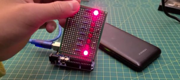
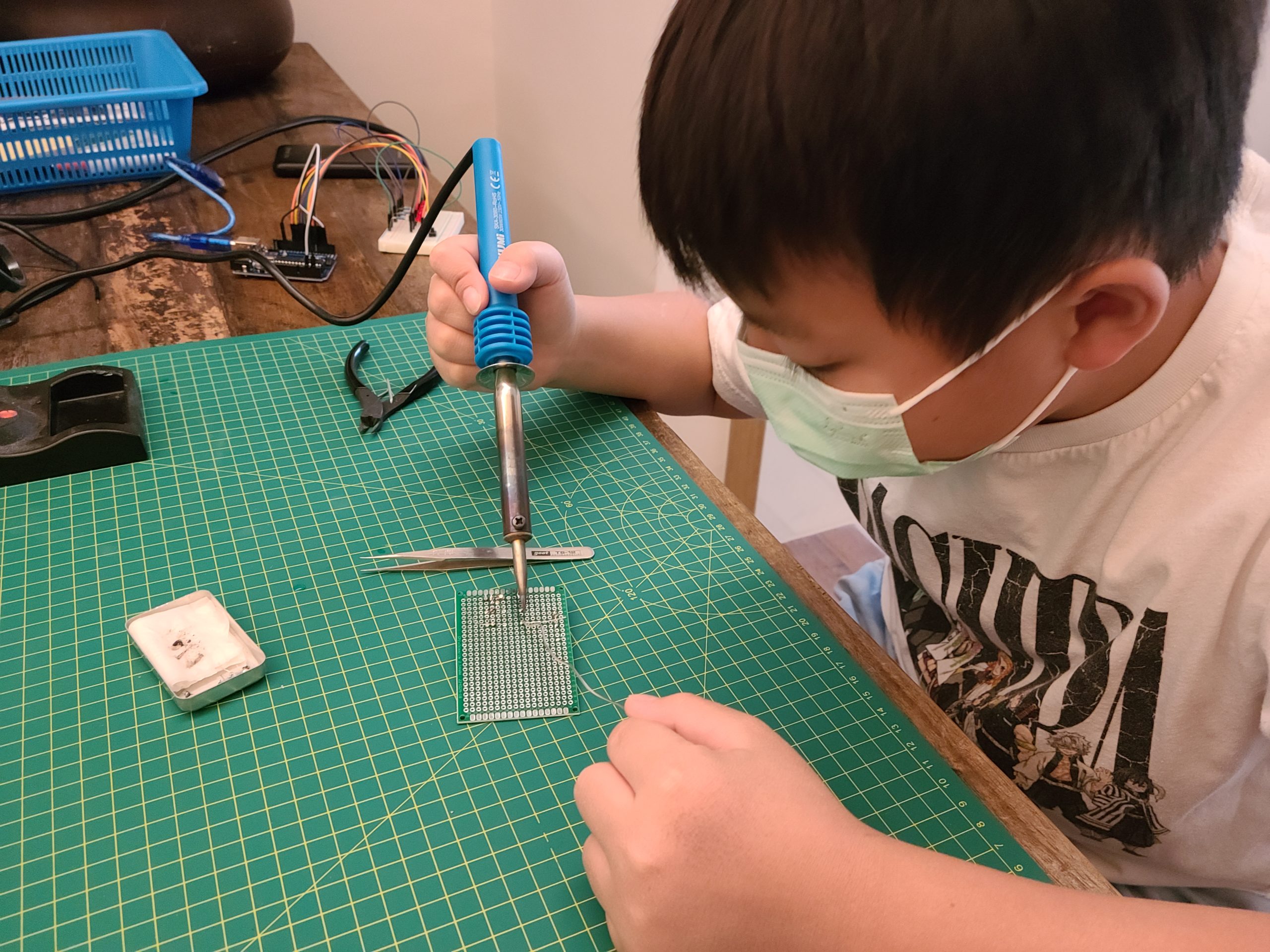
This is our first Arduino project and also our first time to use soldering iron.. XD
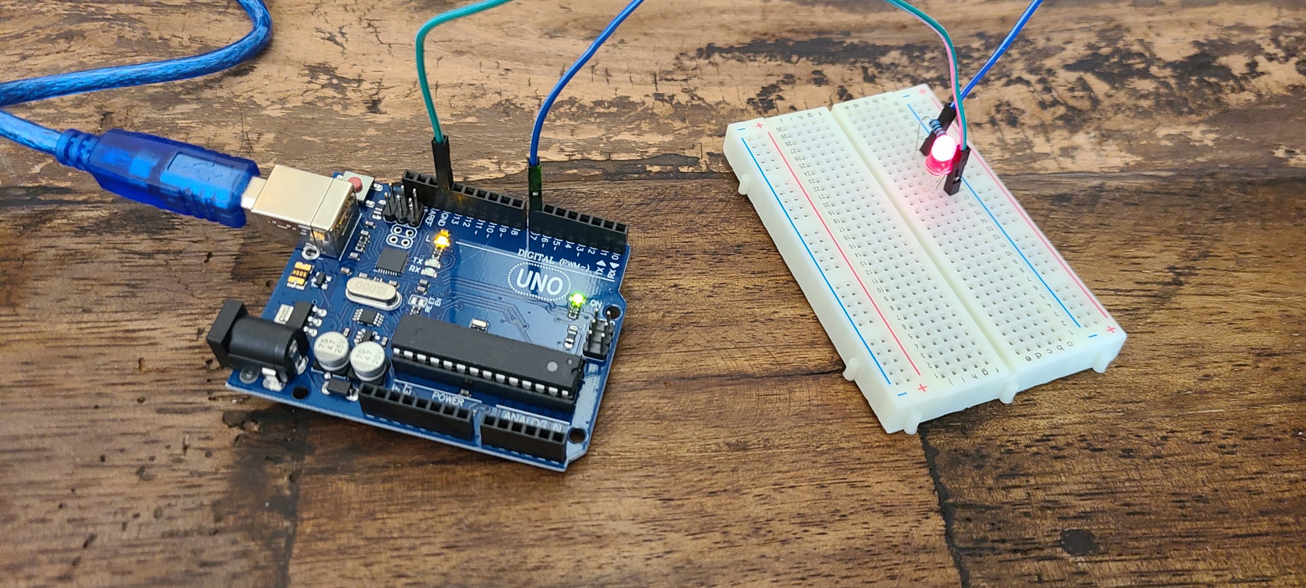
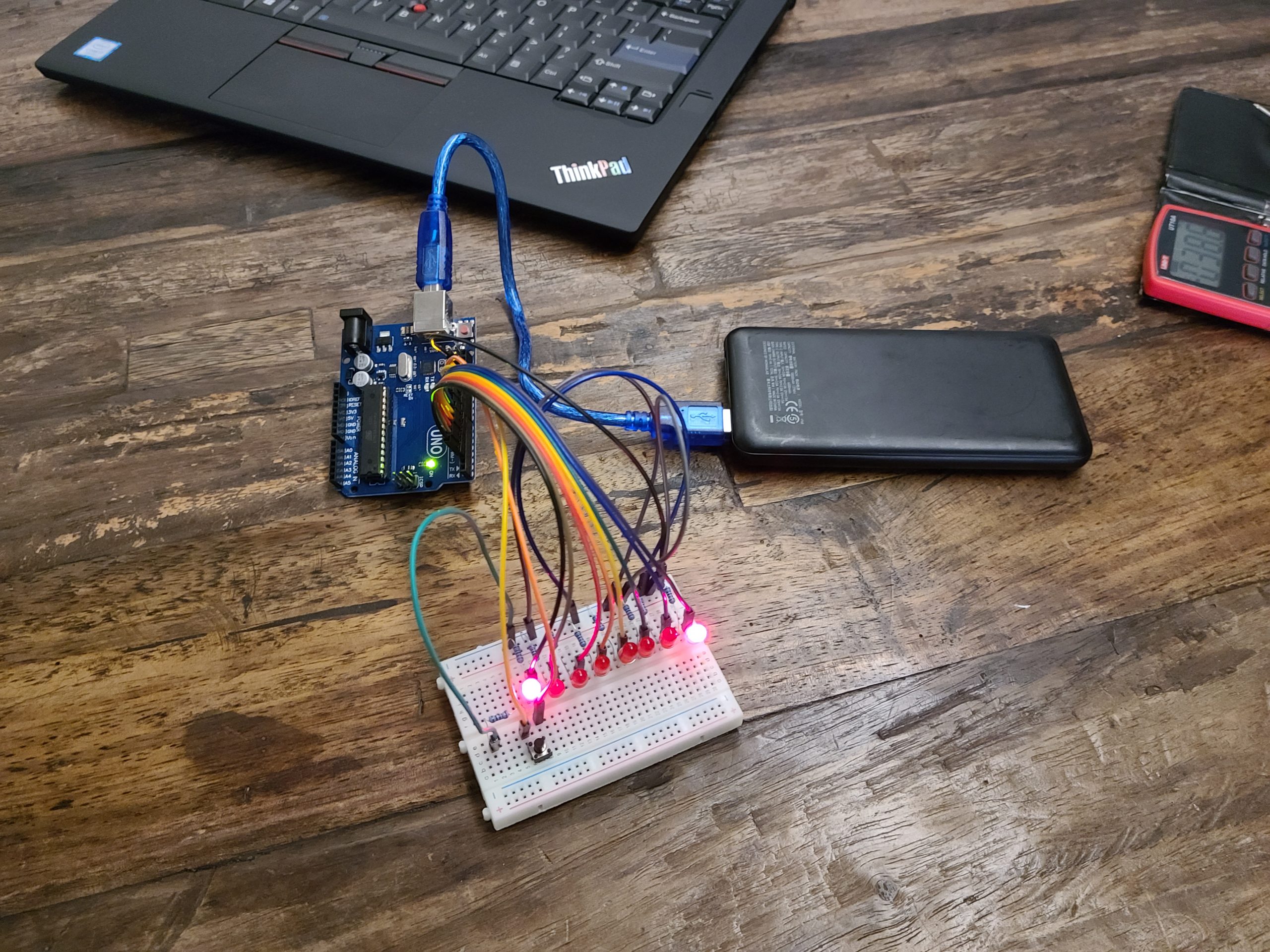
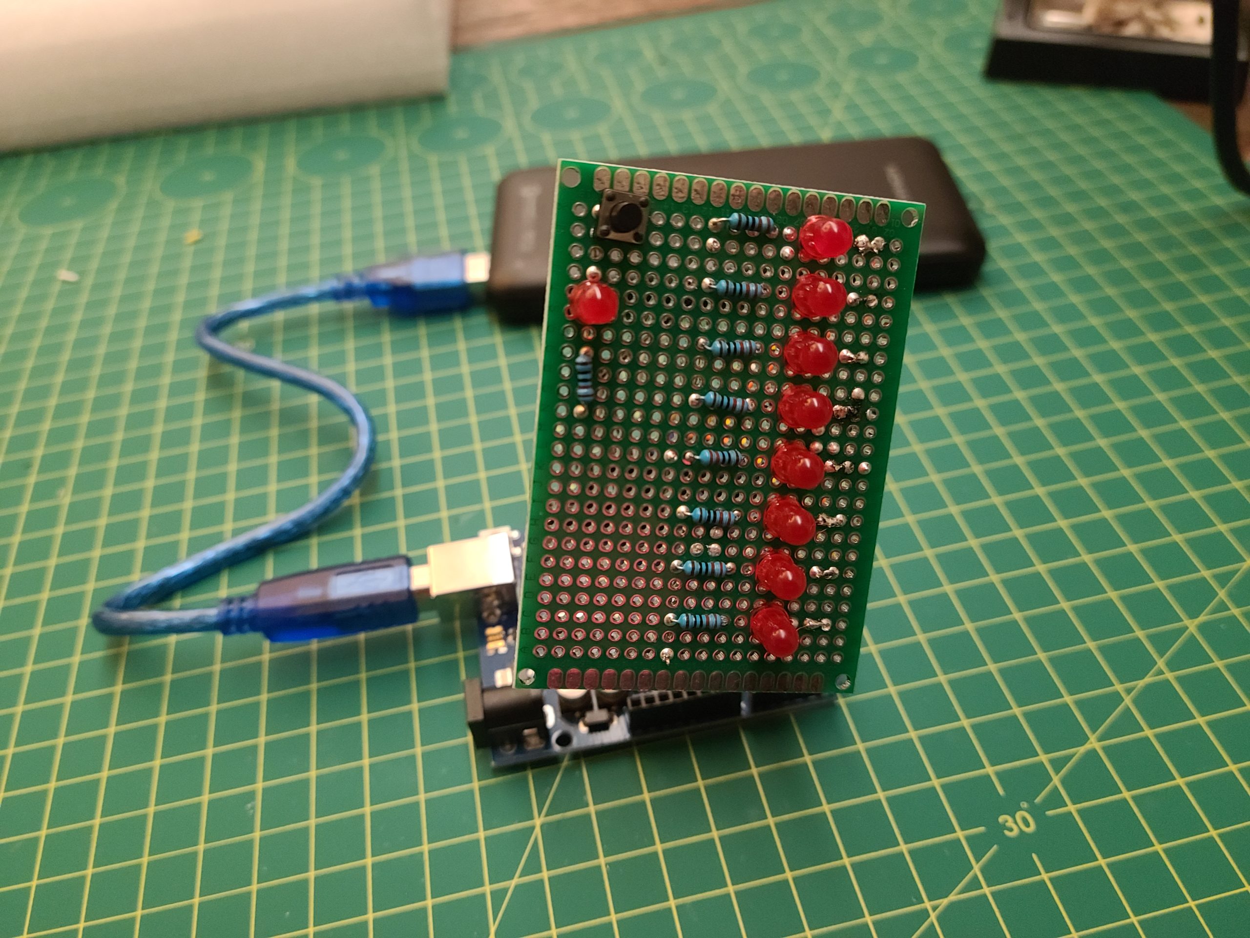
After we learnt some basic idea about the Arduino UNO board and basic LED circuitry, we started to build our first project – LED array. But, keep in mind, always put loading (i.e. resistor) for LED. Otherwise, you will burn it or even damaged the board.
We built LED array circuitry with the ‘bread’ board, so that we can easily adjust and debug the circuitry prior fit them onto a PCB.
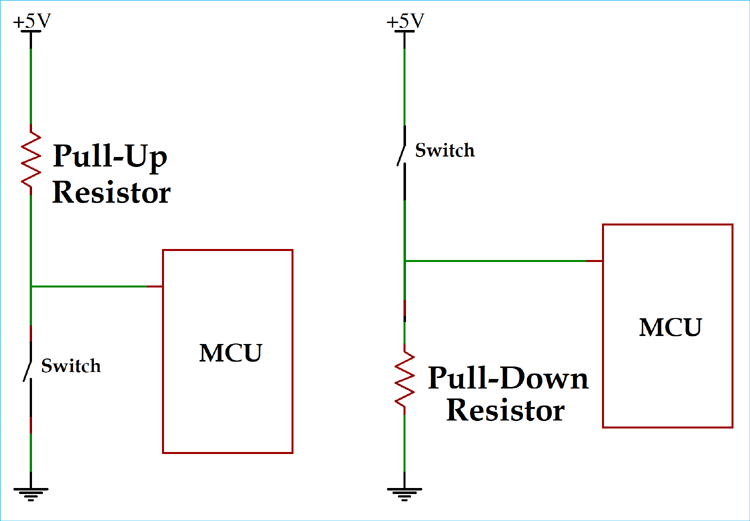
We also learnt how to connect the switch to the input pin with pull-up and pull down resistor concept. So that the input pin will not be floating with uncertain voltage which will induce unstable the result. We used pull-down resistor because we want to trigger the LED pattern when the switch is being pressed.
void turn_on() {

  int Light_effect = 1 ;
  button = digitalRead(10);

  if (button == HIGH ){
   Light_effect = Light_effect + 1;
   if (Light_effect == 4) {
     Light_effect = 1 ;
    }
  }
  if (Light_effect == 1) {
    Light_1();
  }
  if (Light_effect == 2) {
    Light_2();
  }
  if (Light_effect == 3) {
    Light_3();
  }
}
We defined 3 lighting effects by on/off different port of LED in preset sequence. When the switch connect to port 10 is pressed, it will change the light effect value and call the function for the corresponding light effect. Once the light effect 3 is done, it will switch back to the first one. Below is the first light effect, try to create your own and simplify the coding.
Once we confirmed the circuitry is good and the program is running well, we soldered all the components to a double side PCB. We made our first PCBA without being scalded by the soldering iron!!!