Category Archives: LEGO MindStorms

LEGO MindStorms – Znap with PS4 controller

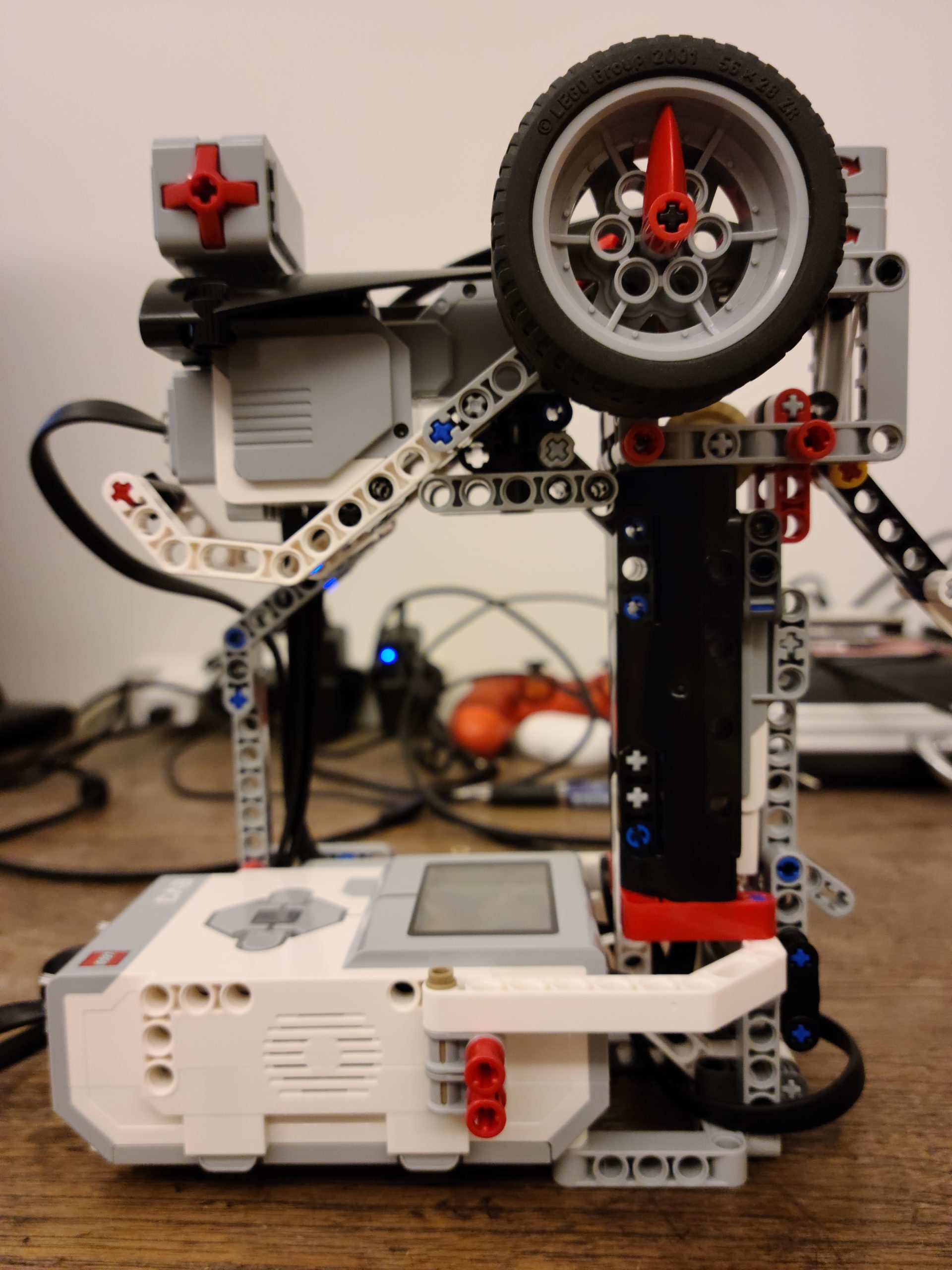
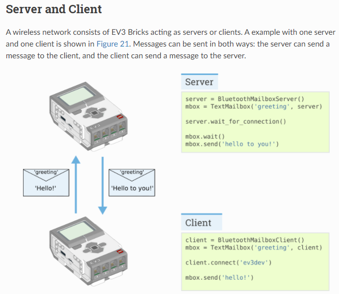
This is an extended project of LEGO MindStorms – Znap with a remote controller, please refer it for the Dog movement and communication between EV3 Bricks.

Linux /dev/input/event*

Thanks for Anton’s Mindstorms Hacks, evdev and Linux Input drivers v1.0 (c) 1999-2001 Vojtech Pavlik, they gave us good idea how Linux deal with inputs.

Since ev3dev is Linux based, when PS4 controller connected to the EV3 Brick via Bluetooth, we can identify the handler from a directory call /dev/input. As shown below, event2, event3 and event4 are created when the PS4 controller is connected.

When we looked into the device detail from /proc/bus/input/devices, we can get the following details,

  • Handler Event 0 = Input0 – LEGO Mindstorms EV3 Speaker
  • Handler Event 1 = Input1 – EV3 Brick Buttons
  • Handler Event 2 = Input2 – Wireless Controller Touchpad
  • Handler Event 3 = Input3 – Wireless Controller Motion Sensors
  • Handler Event 4 = Input4 – Wireless Controller

We are going to use the Wireless Controller to control the Dog, event4 is the target handler to get all inputs information. Based on the information we reviewed, we learnt that event4 contains 16 bytes of data as shown below,

  • tv_sec (long unsigned value) : Time in seconds since epoch at which event occurred.
  • tv_usec (long unsigned value) : Microsecond portion of the timestamp.
  • ev_type (unsigned short) : Event type
  • code (unsigned short) : Event code
  • value (signed long) : Event value

We are using ev_type, code and value to monitor the PS4 controller inputs. It updates real time for any status change, such as button press, button release, joystick movement. Keep in mind, if a button is being held, it will generate a value ‘1’ for once but no additional update until the button is released, then a value ‘0’ will be generated.

[This part was created by Adam]

PS4 Controller mapping with EV3DEV

# Open the PS4 Controller file at /dev/input/event4 in binary mode
infile_path = "/dev/input/event4"
in_file = open(infile_path, "rb")

# Format of the event contains - unsigned long int, unsigned long int, 
# unsigned short, unsigned short, signed int, i.e. LLHHi
FORMAT = 'LLHHi' 
EVENT_SIZE = struct.calcsize(FORMAT)
.
.
.
# Read from the file and unpack into five variable based on the format
event = in_file.read(EVENT_SIZE)
(tv_sec, tv_usec, ev_type, code, value) = struct.unpack(FORMAT, event)

This part is to open the file event4 to import the PS4 Controller values into 5 variables based on the predefined format – ‘LLHHi’. We use ev_type, code and value to identify the action from PS4 Controller.

  • ev_type : There are two main type, type 1 = buttons, type 3 = joystick, dpad and analog trigger
  • code : Which button or joystick being pressed / moved
  • value : The action done, button pressed = 1, released = 0, or analog value from joystick and analog trigger

So, we wrote a small program to identify each codes and values from the PS4 Controller. The result is shown below,

Key mapping as shown below

Type = 1, code & possible value

L1 - 310 (0,1)
L2 - 312 (0,1)
L3 - 317 (0,1)
R1 - 311 (0,1)
R2 - 313 (0,1)
R3 - 318 (0,1)
Triangle - 307 (0,1)
Square - 308 (0,1)
Cross - 304 (0,1)
Circle - 305 (0,1)
Share - 314 (0,1)
Option - 315 (0,1)
PS - 316 (0,1)

Type = 3, code & possible value

Left Stick Y - 1 (Up 0 - Down 255)
Left Stick X - 0 (Left 0 - Right 255)
Right Stick Y - 4 (Up 0 - Down 255)
Right Stick X - 3 (Left 0 - Right 255)
L2 - 2 (0 - 255)
R2 - 5 (0 - 255)
dpad Up & Down - 17 (-1, 0, 1)
dpad Left & Right- 16 (-1, 0, 1)

How does the program work

def PS4_Controller():
    global pressed
    global trigger_dog
    global speed
    global speed_backwards
    global speed_forwards
    global turning
    global out

    while True:        
        # Read from the file and unpack into five variable based on the format
        event = in_file.read(EVENT_SIZE)
        (tv_sec, tv_usec, ev_type, code, value) = struct.unpack(FORMAT, event)
                    
        if ev_type == 1 and code == 311 and value == 1: 
            trigger_dog =  45                  
            out = 1
        if ev_type == 1 and code == 311 and value == 0:
            trigger_dog = 0        
            out = 0

        if ev_type == 1 and code == 310 and value == 1 and out == 0:
            trigger_dog =  35

        if ev_type == 1 and code == 310 and value == 0 and out == 0:
            trigger_dog =  0
                
        if ev_type == 1 and code == 305 and value == 1:
            pressed = True
            
        if ev_type == 1 and code == 305 and value == 0:
            pressed = False
                    
        if ev_type == 3 and code == 5:
            speed_forwards = value * 6
        
        elif ev_type == 3 and code == 2:
            speed_backwards = value * -6

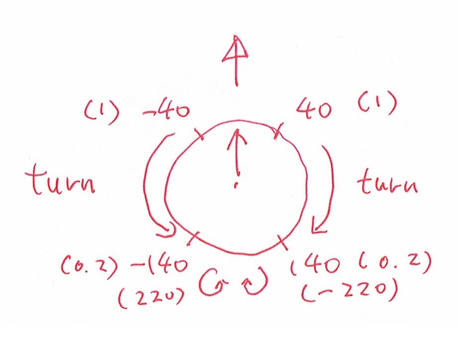
        if ev_type == 3 and code == 0:
            turning = (value*360-(180*255))/255

PS4_Controller_Thread = threading.Thread(target = PS4_Controller)
PS4_Controller_Thread.setDaemon = True
PS4_Controller_Thread.start()
        
bite = 0
while True:

    speed = speed_forwards + speed_backwards    
    print(speed)
    combo(pressed)
    forward(speed,turning)
    bite = Dog_bite(trigger_dog, bite)
    
in_file.close()

Basic Idea

Since we didn’t want to change the program of ‘the Dog’, we replaced the LEGO Controller part, i.e. receiving LEGO Controller result, with a new function to detect the action from the PS4 Controller buttons and joysticks. When corresponding action done on the PS4 Controller, the function will update the variable for ‘the Dog’ to action.

For example, when we press the circle, the function will detect a value of ev_type = 1 , code = 305 and value = 1. Then, it changes the variable ‘Pressed ‘ to True so that ‘the Dog’ will do combo. If we keep pressing the button, the variable ‘Pressed’ will stay True until we released the button.

Parallel Processing

We made the function parallel processing because it can detect all the status changes from the PS4 Controller. If we use normal function, the function will only read the latest actions from the controller that may result missing some of the actions. Especially, if we want to detect button pressed or released.

Global Variable

When we use global variable, the variable change by the parallel progressing function can be read by the program outside. For the PS4_Controller function detects any actions from the controller, it will change the corresponding variable for ‘the Dog’ to respond, just like the LEGO Controller sending message to ‘the Dog’.

Build instruction and the program

We created the program from scratch without referring any example, you can download from below.

Official Build Instruction from LEGO

The Dog

What’s next?

It may be fun if you use PS4 to control the LEGO Elephant, Snake and even with the Stair Climber!!

Moreover, you may try to learn more about event2 & event3 for how to use the controller touchpad and the motion sensor.

LEGO MindStorms – Znap with a remote controller

My dad told us that he wanted a RC car with a professional controller like this… that’s one of his childhood dream.

He was so excited with such professional controller we made…. HOWEVER, we built him this ‘car’… LOL

This is a great project to make use of two bricks and the messaging functions, how we connect the remote Controller with the Dog by feeding different data via different ‘mailbox’ is the key.

Features of the remote controller

Turning Wheel

The function of this wheel is to see how many degrees you turn the wheel. The more you turn the wheel, the higher number you get. If you turn it backwards, it will give you a negative number. Thus, positive number is turning right, negative number is turning left.

Direction Sensor

This is the Direction Sensor, this sensor detects how much you have tilted the handle. When you tilt the controller more forward, the higher number the sensor will give. If you tilt the controller backward, it will give you a negative number. Thus, positive number is going front, negative number is going back.

Calibration

The calibration is quite simple. When starts the program of the controller, just need to ensure the turning wheel back to 12’o clock position for easy control. Then, put the controller on a flat table to ensure the controller start from a horizontal position since we will use it’s tilting to control the ‘Dog’ direction.

Once all set, the program will reset the turning wheel angle and the direction sensor back to zero.

How does the program work?

Communication with different mail boxes

The Controller

SERVER = 'ev3dev2'
client = BluetoothMailboxClient()
client.connect(SERVER)

mbox = TextMailbox('Dog', client)
trigger_mbox = NumericMailbox('Trigger', client)
turn_mbox = NumericMailbox('Turn', client)
combo_mbox = LogicMailbox('Combo', client)
speed_mbox = NumericMailbox('Speed', client)

The Dog

server = BluetoothMailboxServer()
server.wait_for_connection()

mbox = TextMailbox('Dog', server)
trigger_mbox = NumericMailbox('Trigger', server)
turn_mbox = NumericMailbox('Turn', server)
combo_mbox = LogicMailbox('Combo', server)
speed_mbox = NumericMailbox('Speed', server)

These two programs connect two EV3 bricks via Bluetooth. We made different mailboxes to separate the communication between two bricks. For example, if we want to send information or message to tell the Dog how’s Turning Wheel result, it will be using mailbox ‘Turn’. So, we can perform very dedicate communication channels between the Controller and the Dog, make it easy way than using just one mailbox.

Messaging Synchronization

The Controller

# Sychronize the mail box between the robot and the remote
# Ensure the robot get new mail from the remote before start
# Once the robot get the new mail, will confirm Ready and OK to start
i = 0
while mbox.read() != 'Ready':
    trigger_mbox.send(i)
    turn_mbox.send(i)
    combo_mbox.send(i)
    speed_mbox.send(i)
    i = not i
combo_mbox.send(False)
mbox.send('OK')

The Dog

# Sychronize the mail box between the robot and the remote
# Ensure the robot get new mail from the remote before start
# Once the robot get the new mail, will confirm Ready and OK to start
trigger_mbox.wait_new()
turn_mbox.wait_new()
combo_mbox.wait_new()
speed_mbox.wait_new()
mbox.send('Ready')
mbox.wait()

Since we cannot ensure two bricks starting at the same time and same speed, we did a synchronization process to confirm two bricks ‘hand shake’ prior to start. We make the Dog mailboxes to read new mails only, it will wait until the Controller sends a new message to every mailboxes. Once new mails received, the Dog confirm ‘Ready’ and the Controller will reply by ‘OK’. Then, start the process.

It’s important. If the Dog runs faster, a ‘NONE’ message will be read because the Controller have not sent any messages yet. ‘NONE’ is not an value to be processed, which will induce an error.

We set ‘combo_mbox.send(False)’ because we don’t know the last message sent from the Controller is ‘1’ or ‘0’. If we don’t add this, it will result as a glitch that the Dog will randomly do Combo at start.

The Controller

while True:
    if mbox.read() == 'OK':
        
        combo_mbox.send(combo_sensor.pressed())
        turn_mbox.send(turn_sensor.angle())
        speed_mbox.send(speed_sensor.angle())
        trigger_mbox.send(trigger_sensor.angle())

The Dog

while True:
    # Stop the remote sending new data which will induce overflow
    # If wait time too short, it will be always 'Wait' or send 
    # duplicate result
    mbox.send('OK') 
    wait(30)
    mbox.send('Wait') 

    pressed = combo_mbox.read()
    combo(pressed)
    
    turning = turn_mbox.read()
    speed = speed_mbox.read()
    forward(speed * 12, turning)

    trigger_dog = trigger_mbox.read()
    bite = Dog_bite(trigger_dog, bite)

In the most beginning we setup the program, we had the Controller keep sending the reading to the Dog. However, it would result as errors because too much information fed to the Dog. So, we also added a ‘hand shake’ process to ensure the Controller to send the reading once the Dog is ready.

Direction Control

def forward(speed, turn_angle):
    
    # When turn sensor between -40 to 40, go straight
    # Turn right in scale between 40 to 140
    # Turn left in scale between -40 to -140
    # Self rotate to right between 140 to 220
    # Self rotate to left between -140 to -220
    # If the user turn over the limit 220 or -220, the robot will stop
    right_speed_alternator = 1
    left_speed_alternator = 1
    
    if turn_angle < 40 and turn_angle > -40:
        left_speed_alternator = 1
        right_speed_alternator = 1

    elif turn_angle > 40 and turn_angle < 140:
        right_speed_alternator = 1 - (turn_angle - 40)/100*0.8
        
    elif turn_angle < -40 and turn_angle > -140:
        left_speed_alternator = 1 - (turn_angle + 40)/100*-0.8

    elif turn_angle > 140 and turn_angle < 220:
        right_speed_alternator = -1 
        left_speed_alternator = 1

    elif turn_angle < -140 and turn_angle > -220:
        right_speed_alternator = 1 
        left_speed_alternator = -1

    elif turn_angle > 220 or turn_angle < -220:
        right_speed_alternator = 0
        left_speed_alternator = 0
        ev3.speaker.beep()        

    if speed < 120 and speed > -120 :
        right_wheel.hold()
        left_wheel.hold()
    else:
        right_wheel.run(speed * right_speed_alternator)
        left_wheel.run(speed * left_speed_alternator)

Forward, Backwards & Hold

In this function, we make the robot move according to the gyro sensor angle. How fast the Dog to move is the angle multiply by 12. Thus, the gyro sensor tilts more forward, it moves faster. If it tilts backward, it goes reverse. We made the robot hold when the angle is between -10 to 10 (-120 to 120) .

Turning Direction

See above picture, we want the Dog to turn when we rotate the Turning Wheel from the Controller. It will start turning right when Turning Wheel is sitting between 40deg to 140deg or turning left between -40deg to -140deg. We used a formula to calculate how fast we want the robot to turn, the right wheel formula is “right_speed_alternator = 1 – (turn_angle – 40)/100*0.8” and the left wheel formula is “left_speed_alternator = 1 – (turn_angle + 40)/100*-0.8”. So, the more you rotate the Turning Wheel, the bigger of the speed alternator will be resulted. The Dog will turn because we alternate the Dog’s wheels in different speed.

If you turn the wheel over 180 degrees (or -180 degrees), the Dog will stop and beep.

Bite Control

def Dog_bite(angry, bited):
    if angry > 40 and bited == 0:
        forward(0,0)
        ev3.speaker.play_file(SoundFile.DOG_BARK_2)
        head_control.run(1000)
        return 1
    elif angry < 40 and angry > 15 and bited == 0:
        forward(0,0)
        ev3.speaker.play_file(SoundFile.DOG_GROWL)
        return bited
    elif angry < 15 and bited == 1:
        head_control.run(-1000)
        wait(500)
        head_control.run(0)        
        return 0
    elif angry > 40 and bited == 1:
        forward(0,0)
        return bited
    else:
        return bited

This function we made the biting part of the dog. If the Controller trigger is held, it will bite. It will growl when the trigger is on the half-way. When we release the trigger, the dog will return to it’s normal form.

Since we don’t want the Dog keep moving when growl or bite. We setup a variable call ‘bited’ to ensure that the Dog will keep in bite position without any movement. Once we release the trigger, the Dog will move again.

Build instruction and the program

We created the program from scratch without referring any example, you can download from below.

Official Build Instruction from LEGO

What’s next?

Make the dog becoming self-navigation, it already a ultrasonic sensor in its’ front and we have not used this

Using a PS4 controller instead of the LEGO controller

Voice control with Alexa?

LEGO MindStorms – Rubik Solver MindCub3r

For this project, we have decided to build a Rubik cube solver. This Rubik cube solver was not easy to build, we came over lots of obstacle in the way, such as motor jammed, sensor too weak to detect cube and some building mistakes. It was hard work over coming it but when everything is fixed, the result is very satisfying. For this time, we did not make our own program because its too complicated. We are currently trying hard to make our own program…. but…

Credits to David Gilday for coming up with this amazing masterpiece. I think its really amazing of how he can manage to make such a complicated robot and developed the software.

If you are looking for build instructions, then please visit this website→http://mindcuber.com/mindcub3r/mindcub3r.html

Features of the Mindcub3r

Rotation Tray

The rotation tray is used for putting a cube in the place. It is also capable of rotating the cube, so that the colour sensor can scan every tiles of the cube. When cube flipper hold the cube, the rotation tray can rotate the bottom layer of the cube.

Colour Sensor

The colour sensor is used to detect colour the tiles. When the program start, the robot will be using the rotation tray, cube flipper and color sensor to scan all tiles on all six face.

Based on the information it scanned, the robot will calculate the steps to solve the cube. Most of the time, it will take ~24 steps.

Cube Flipper

The cube flipper is used to flip the cube backward to make the bottom side face to right, i.e. close to color sensor. The cube flipper can also hold the cube so the rotation tray can move the bottom layer of the cube.

Cube Detection

The cube detection is much straight forward. Judging by it’s name, its obvious that the program will start once the cube is detected.

Note: I have tilted the cube a bit forward because the sensor is too weak to detect the cube. If you ever have the same problem, just tilt the cube detection’s support a bit forward.

Attention!

Cube Surface and color reflection

Different colour surface can make a difference. If the cube is quite dull, then colour sensor signal will be weaker because there is not much reflections. At the end, some colours will be misplaced while the robot misjudge some colors. So keep in mind that only cubes with shinier tiles works.

Special Pattern

Other than fixing and mixing the cube, the robot is also capable of making different unique patterns.

There are a total of 5 patterns:

  1. Checkerboard
  2. Cube-in-cube
  3. Six-spot
  4. Snake
  5. Superflip

LEGO MindStorms – Spinner Factory

When we built the factory, we thought that the EV3 Home (Scratch base) can support two bricks. However, no ever how much information we read, it is not what we expected. We were trying to modify factory by adding additional color sensor, so that we can use two separated program to control this, we really don’t want to deal with EV3-G (LabView) even it support EV3 daisy chain. Finally, we decided to go for EV3dev and it opened our eyes.

Go ahead to try EV3DEV2, Python is easy if you already know Scratch based programming. Don’t hesitating, start from PyBricks, the official one.

Features of the factory

Head control – The first function is moving the head up and down getting the spinner parts. The second function is switching the tool for the head, one is to pickup the spinner parts and place it on the spinner holder, the other one is the spinning tool which will spin the finished product.

Color Sensor – This Color sensor is used for detecting the color, so that we can make the bridge go in the sequence you picked. For example, if you pick blue, green, yellow, and red, then the bridge will go in the order you have picked. We have also changed the color tags location, so that it will be easier to program the movement part and pickup the spinner part right at the spot where the bridge stops. The original design by LEGO will make it harder because you have to calculate how far the bridge need to travel after detecting the color tag. But, it is easier for operator to identify the part position.

Spinner control – This is used to release the spinner after it was spun and it also controls the spin lock which lets the spinner lock it in place prior it can be spun. It works by using the motor to turn the red handle up to unlock the spin lock and let it spin. The second step is turning the handle to it’s maximum to release the spinner after it is spun.

However, we made some improvement by moving the bridge ahead to push the handle to maximum instead of using the spinner control. So that the spinner will not hit the the bridge wheels.

Calibration

The Bridge

def bridge_position():
    bridge_move(-180)
    
    while True:
        if rail_color_detect() == 1:
            bridge_move(0)
            ev3.speaker.beep()
            ev3.speaker.beep()
            break
    bridge_move(180) # Prepare a position to call for head calibration
    wait(600)
    bridge_move(0)
    mbox.send('Calibration')
    mbox.wait()
    bridge_move(-180)
    while True:
        if rail_color_detect() == 1:
            bridge_move(0)
            ev3.speaker.beep()
            ev3.speaker.beep()
            break    

The Head

def calibration():
    # Height Control Calibration, max. drive = -526, best pickup position = -490
    height_control.dc(10)
    height_control.run_until_stalled(500,Stop.HOLD,50)
    height_control.reset_angle(0)
    
    # Switch tool : 200 is spinning tool 0 is pickup tool
    # Use 300 to hold the spinner, -300 to release, i.e. pickup tool
    switch_tools.run_until_stalled(-100,Stop.HOLD)
    spinning_tool.run_angle(500,-300,Stop.HOLD)

In the bridge program we made the bridge go back to the first color which is white (we added white ourselves), when the color sensor detects white, it will stop the bridge and move half a step forward whilst communicating with another program that controls the head. When the head received a message saying “calibration” the program will call the calibration program that we have defined as a function. In the function “calibration” we made the height of the head reset to the max which we made it go up to the top, after resetting the height of the head, we switched the tool back to the pickup tool, then we reset the pickup tool by opening the claw so that it can pick up the spinner. Then, the bridge will return the zero position, i.e. the white tag.

How does the program work?

It is not difficult to create the program from moving the bridge, control the head. However, it took us hours to fine tune all the parameters and settings.

Communication

Since this factory using two EV3 Bricks. Using EV3-G (LabView) can support Daisy Chain, i.e. one program to control multiple devices. However, we don’t want to deal with EV3-G anymore and EV3 Classroom just support one device. So, we go for EV3DEV, we pair two EV3 Bricks via Bluetooth and communicate by messaging each others. You can refer to these link for EV3DEV Bluetooth messaging.

Color Detection

# Define the functions
def rail_color_detect():# 1 - White, 2 - Yellow, 3 - Blue, 4 - Green, 5 - Red, 0 - unstable, 99 - others
    for i in range(0,300):
        if i == 0:
            first_color = rail_detector.color()
        if rail_detector.color() != first_color:
            return 0
    if first_color == Color.WHITE:
        return 1
    if first_color == Color.YELLOW:
        return 2
    if first_color == Color.BLUE:
        return 3
    if first_color == Color.GREEN:
        return 4
    if first_color == Color.RED:
        return 5
    return 99

When we developed the program, we found that LEGO color sensor is running unstable, it would provide incorrect color (i.e. noise) occasionally and make our program actioning wrongly. To fix the color sensor misjudgment, we created a color detect function to detect the color 300 times. If all 300 detections are the same, then we can confirm the color detect correctly and return the color code – 1. White, 2. Yellow, 3. Blue, 4. Green and 5. Red. For wrong color detect, it will be 0. 99 for others.

The Bridge

# Start of the main program            
ev3.speaker.beep()
bridge_position()

ev3.speaker.set_volume(100)
ev3.speaker.say("Scan the color now")
color_seq = []
color_selection()

ev3.speaker.beep()

for i in range(0,4):
    bridge_move(180)

    while True:        
        if rail_color_detect() == color_seq[i]:
            bridge_move(0)
            mbox.send('Pickup')
            mbox.wait()
            
            bridge_move(-180)
            while True:
                if rail_color_detect() == 1:
                    bridge_move(0)
                    break
                        
            mbox.send('Release')
            mbox.wait()
            break

mbox.send('Spin')
mbox.wait()
bridge_move(1500)
wait(1000)
bridge_move(0)
mbox.send('All Done')

In this program we reset the bridge to the starting point at “the white tag”, then we scan the color sequence that we want to pickup the spinner part in. The next part we make the bridge go to the color tag in the sequence, then call the head to pickup the spinner part. After it picks up the spinner part, the head will send a message back to the bridge and it will go back to the first tag “white” and again calls the head to releases the spinner part. These steps will be repeated until last part is placed.

The Head

while True:
    mbox.wait()
    message = mbox.read()    
    if message == 'Calibration':
        calibration()
    if message == 'Pickup':
        pickup_parts() 
    if message == 'Release':
        release_parts()
    if message == 'Spin':
        spin_spinner()
    if message == 'All Done':
        break    
    mbox.send('Done')

The head receive a message from the bridge, if the message matches one of the defined message, it will do the corresponding function, such as Pickup – pickup the spinner part. Once the action is done, a message ‘Done’ will send back to the head to confirm that it’s finished.

Pickup Part

def pickup_parts():
    height_control.run_angle(500,-460)
    spinning_tool.run_angle(1000,300,Stop.HOLD)
    height_control.run_angle(500,460)

That’s pretty simple, makes the head go down, pickup the spinner, then go up.

Release Part

def release_parts():
    height_control.run_angle(500,-150)
    spinning_tool.stop()
    wait(300)
    switch_tools.run_angle(500,20,Stop.HOLD,wait=True)
    spinning_tool.run_angle(500,-300)
    switch_tools.run_angle(500,-20)
    height_control.run_angle(500,150)

In this function we made the head go down, adjust the pickup tool angle, release the part , then go up. Why do we need to adjust the tool angle? It is because when the bridge moves on the rail, the vibration will tilt the spinner holder a bit and causing the positioning to be wrong for the part placement, so we adjust the tool angle to compensate this.

Start the spinner and release it

def spin_spinner():
    switch_tools.run_until_stalled(1000)
    switch_tools.hold()
    height_control.run_angle(50,-130,Stop.HOLD,wait=False)
            
    for i in range(0,6):
        spinning_tool.run_angle(100,-30)
        spinning_tool.run_angle(100, 30)
    
    release_tool.run_angle(500,170)
    switch_tools.stop()
    spinning_tool.dc(-100) # Must rotate in Clockwise Direction, otherwise the head will be mis-aligned
    wait(5000)
    height_control.run_angle(1500,130,Stop.HOLD,wait=True)
    # release_tool.run_angle(1500,60)
    mbox.send('Move!')
    spinning_tool.dc(0) 

It switch the tool switcher to the spinning tool. Then we make the head go down to a height that is considerable for the spinner to spin perfectly. While the head goes down the spinning tool will turn left & right for 10 times ( this is for locking in the angle so we get a better spinning angle). After the spinning tool locks on the spinner, it will spin in 1500 rotation per seconds for 5 seconds, then the bridge will move back quickly. When the bridge move back it will trigger the spinner controller to release the spinner. Originally, the spinner controller should be trigger by the handle. However, the spinner will hit the bridge wheel and failed the mission. So, we move the bridge front to avoid it.

Build instruction and the program

We created the program from scratch without referring any example, you can download from below.

LEGO official build instruction

LEGO MindStorms – Stair Climber

This project is so funny and cool, we are controlling a robot which contain the cart and the lifting arm, so that it can climb stairs. Looks like a Mars rover!!

Features of the robot

Gyro Sensor – It is used to detect or reference the degrees that the project is tilting towards. If the object is tilting forward, then the numbers will be positive, it will be negative if it is tilting backwards. How do we use this gyro sensor in our robot? It can be used to set a limit on how much you should tilt. For example, you want your cart to tilt to -15 then stop and reset degrees counter, then the gyro sensor will come in handy because it detects how much the robot tilts.

Touch sensor – It is used to send signals when something goes in contact with it. In this stair climbing project, the touch sensor is used as a calibration. When the top part come in contact with the touch sensor, then it will reset the degrees counter and it will return to the straight form. Why is the calibration important? The calibration is used to limit how much the belt should go. If the belt goes over the limit, then the motor will malfunction or in worst scenario, even break the motor.

‘Little Fella’ – This little guy’s function is kind of confusing, I thought it was just a noise maker at first. This little guy’s function was unknown until we tested the project. When we tried our first run, we realize that the little guy has the function to stop the middle wheel from moving backwards. What a powerful little fella…

Calibration

This program is the calibration part. It is the most important part of the whole program, because we always need to check the limit and identify the zero point, so that it will not mess up the motor movement because of wrong degree number.

Moreover, we also identify the gyro sensor horizontal level and rest to zero when it sitting on the floor.

So what I did in this program is that I made the lifting arm go up until it presses the button, when it presses the button it will reset the degrees counted so that the top will be the zero point, then the lifting arm goes down by moving the motor clockwise by 2900 degrees. (we got it manually) then we reset the Gyro sensor since it is horizontal to the floor.

Stair Climber Movement concept

When the stair climber moves forward and hit the wall, the front wheel will make the cart going upward and result as tiling up. Once we detect tiling for a certain degree, we will activate the lifting arm to push the cart upwards until it reach the top of stair, we call this landing. Once the cart landed, it will be no longer tilting upward, i.e. no tilting or very small tilting. Then, we will collect the lifting arm to the top of stair and moving forward for the next climbing.

IMPORTANT! When we doing above action, we need to control the back wheel action carefully. If back wheel pushing too much, the cart will flip over because of the center of gravity changed.

How’s the program working?

  1. Check whether the gyro sensor detects tiling and if it is more than 15 degree, i.e. the forward wheel rotate against the wall and the head tilt up. If yes, it will start the lifting action 2.
  2. Determine if the cart landed or the lifting arm reach the max. Otherwise, keep the arm lifting action.
  3. We need to balance the speed of the wheels. If we make the back wheel too fast, the cart will flip over while going up the stairs. If the back wheel goes too slow, the cart will be too slow for the landing and it will be stuck at the edge of the stairs. We also need to make the front wheel rotating speed synchronized to the lifting arm speed.
  4. We have to balance the cart if it is tilting so much like it is going to fall. We have to stop the back wheel so that the cart will not keep moving forward, i.e. change the center of gravity. So, we stop the back wheel for a certain tilting angle that the cart may flip over.
  5. We need to stop the wheels before the lifting arm move up or else the lifting arm is going to snap. After stopping the wheels, we pull the lifting arm back up to the original place. Then, the stair climber keep going for next stair.

Build instruction and the program

We created the program from scratch without referring any example, you can download from below.

LEGO Offical build instruction

I also attached the link for LEGO EV3 Classroom for your quick reference, click here.

LEGO MindStorms – Elephant

https://www.youtube.com/watch?v=tW2K-LxkUUQ

Calibration

The best part for this elephant is installed two sensors to detect the trunk and the head movement, so that we can program this to avoid the motor over-driving the head and trunk to induce unnecessary damaged. Calibration is very important for machine and robot, identify the zero (or required) position, so that they can be working within the expected range and accuracy. The calibration will run every time when the elephant start because we got unknown starting position of the head and trunk. Once, it dance, it will be always the same.

As you can see above, there are two sensors installed – color sensor and touch sensor.

During the head is moving up, the color sensor is detecting the color in it’s front. When the elephant raises it’s head up to the limit, a red color should be detected. So, we did the coding as below.

When we setup a robot, we actually need to do some manual work to understanding your robot. Prior we wrote this calibration program, we analysis the movement of the head to understand the moving direction and the stroke of the head, keep those as preset ‘parameter’ – we got ‘head (D) down’ is ‘-800’.

Then, we start the program in a loop by detecting the color sensor until it detect ‘red’. Before the red color being detect, the motor controlling the head keep moving up for every 10 degree, so that the head will not be crushed.

Once red color detected, the movement will stop and the motor degree count reset to the ‘zero’ position, so that we can control the elephant with a range of 0 to -800.


Same as what we done for the head calibration, we also need to do some manual work to understand the moving direction and the stroke of the trunk, we got ‘trunk (B) down’ is ‘900’.

Using exactly the same coding for the calibration but change the detective sensor from color sensor to touch sensor because touch sensor was installed when the trunk move up and it will hit the touch sensor.

Again, once the touch sensor is touched, stop the raising trunk and reset the degrees count, set this as ‘zero’ position.

Build instruction and the program

We created the program from scratch without referring any example, you can download from below.

Our first LEGO EV3 robot

We are so exciting to assembly the first robot hand!!!

The old EV3 programming language is too ‘engineering’ and not easy…

Alex created the program, he explains how to program the robot to realize the command from the remote

Finally, a robot operator competition!! Who won?