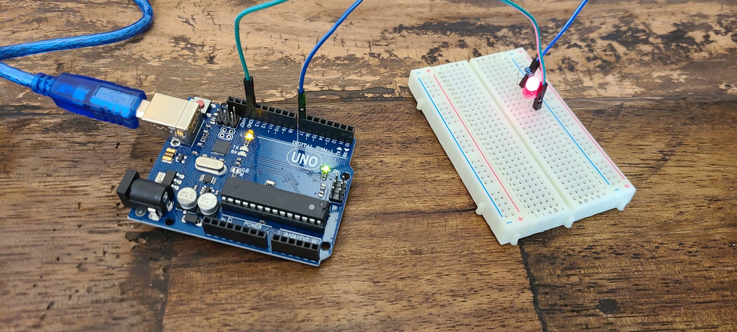
After we learnt some basic idea about the Arduino UNO board and basic LED circuitry, we started to build our first project – LED array. But, keep in mind, always put loading (i.e. resistor) for LED. Otherwise, you will burn it or even damaged the board.
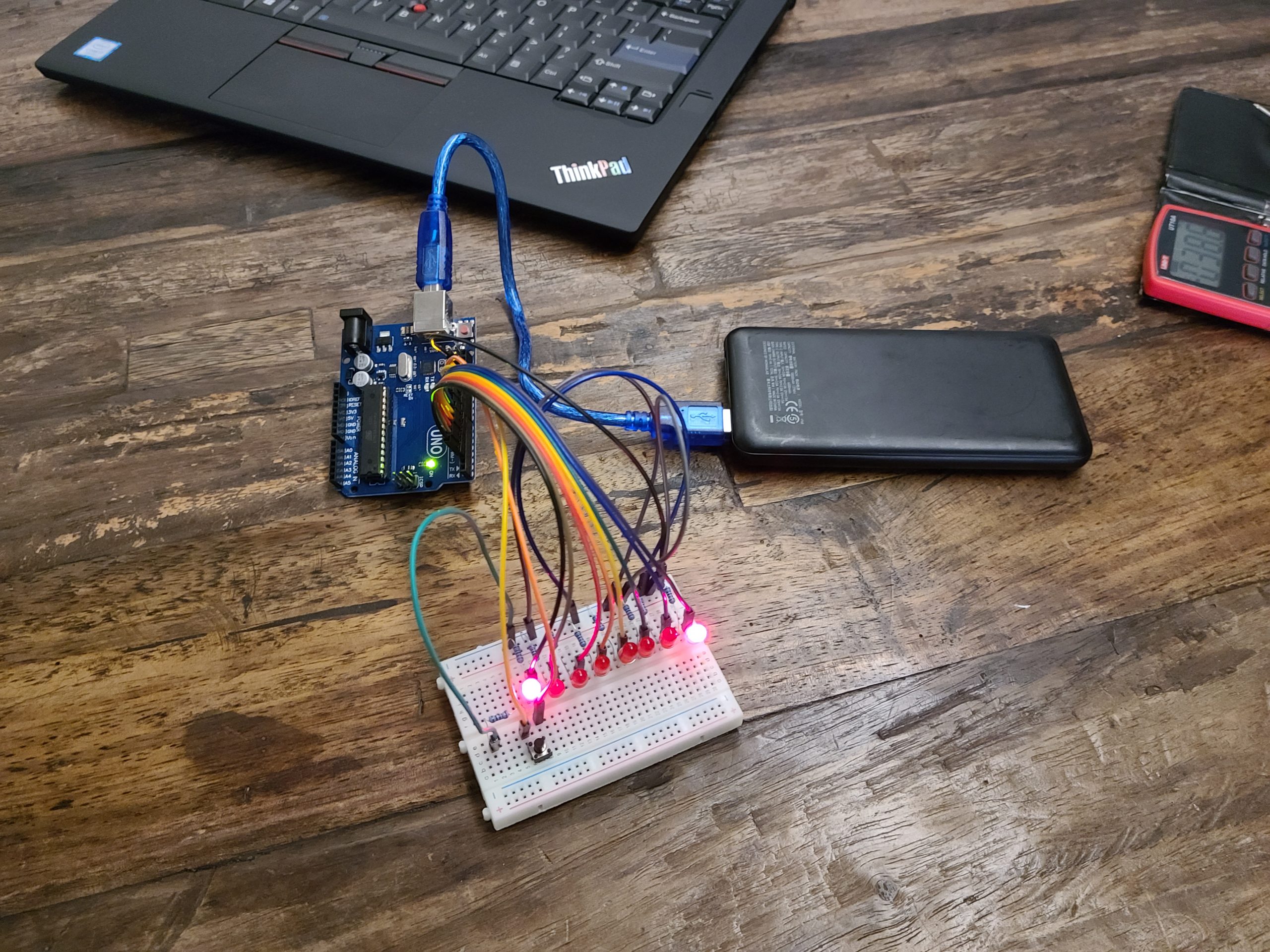
We built LED array circuitry with the ‘bread’ board, so that we can easily adjust and debug the circuitry prior fit them onto a PCB.
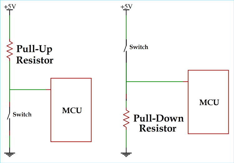
We also learnt how to connect the switch to the input pin with pull-up and pull down resistor concept. So that the input pin will not be floating with uncertain voltage which will induce unstable the result. We used pull-down resistor because we want to trigger the LED pattern when the switch is being pressed.
void turn_on() {

  int Light_effect = 1 ;
  button = digitalRead(10);

  if (button == HIGH ){
   Light_effect = Light_effect + 1;
   if (Light_effect == 4) {
     Light_effect = 1 ;
    }
  }
  if (Light_effect == 1) {
    Light_1();
  }
  if (Light_effect == 2) {
    Light_2();
  }
  if (Light_effect == 3) {
    Light_3();
  }
}
We defined 3 lighting effects by on/off different port of LED in preset sequence. When the switch connect to port 10 is pressed, it will change the light effect value and call the function for the corresponding light effect. Once the light effect 3 is done, it will switch back to the first one. Below is the first light effect, try to create your own and simplify the coding.
void Light_1() {

  digitalWrite (9,HIGH) ;
  delay (100) ;
  digitalWrite (8,HIGH) ;
  delay (100) ;
  digitalWrite (7,HIGH) ;
  delay (100) ;
  digitalWrite (6,HIGH) ;
  delay (100) ;
  digitalWrite (5,HIGH) ;
  delay (100) ;
  digitalWrite (4,HIGH) ;
  delay (100) ;
  digitalWrite (3,HIGH) ;
  delay (100) ;
  digitalWrite (2,HIGH) ;
  delay (100) ;
  digitalWrite (9,LOW) ;
  delay (100) ;
  digitalWrite (8,LOW) ;
  delay (100) ;
  digitalWrite (7,LOW) ;
  delay (100) ;
  digitalWrite (6,LOW) ;
  delay (100) ;
  digitalWrite (5,LOW) ;
  delay (100) ;
  digitalWrite (4,LOW) ;
  delay (100) ;
  digitalWrite (3,LOW) ;
  delay (100) ;
  digitalWrite (2,LOW) ;
  delay (100) ;
}
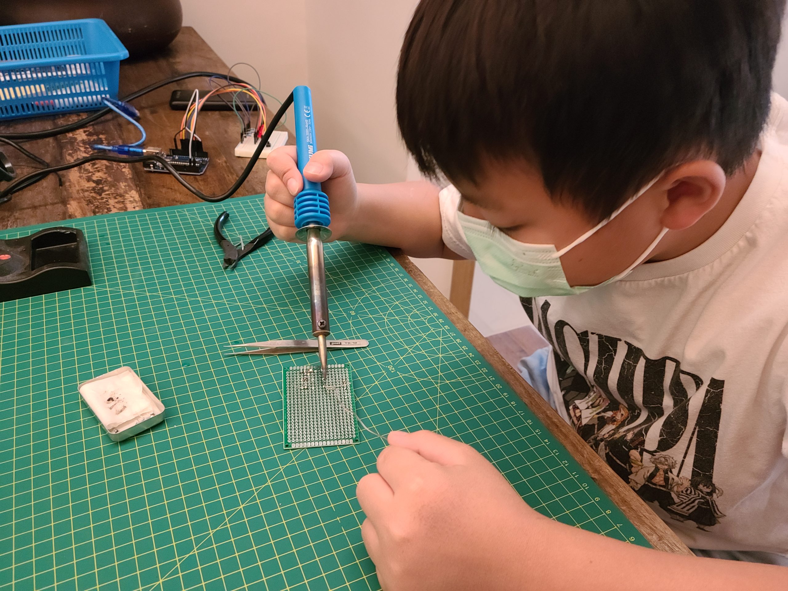
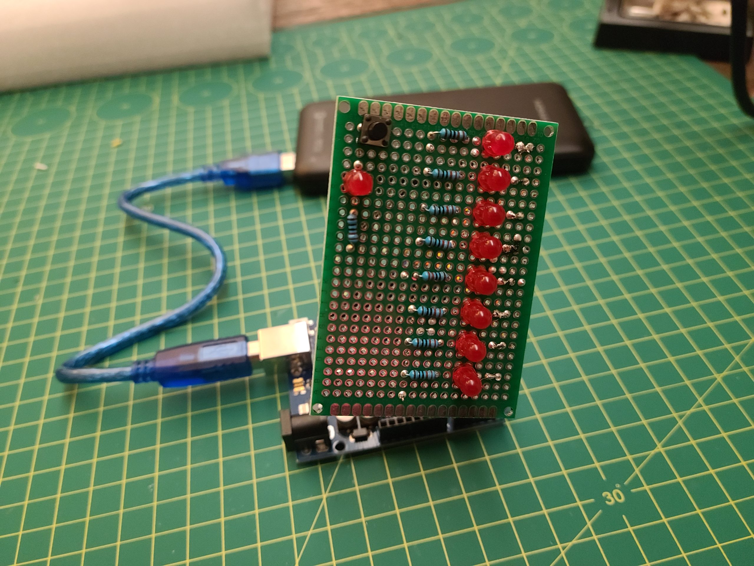
Once we confirmed the circuitry is good and the program is running well, we soldered all the components to a double side PCB. We made our first PCBA without being scalded by the soldering iron!!!