When we built the factory, we thought that the EV3 Home (Scratch base) can support two bricks. However, no ever how much information we read, it is not what we expected. We were trying to modify factory by adding additional color sensor, so that we can use two separated program to control this, we really don’t want to deal with EV3-G (LabView) even it support EV3 daisy chain. Finally, we decided to go for EV3dev and it opened our eyes.
Go ahead to try EV3DEV2, Python is easy if you already know Scratch based programming. Don’t hesitating, start from PyBricks, the official one.
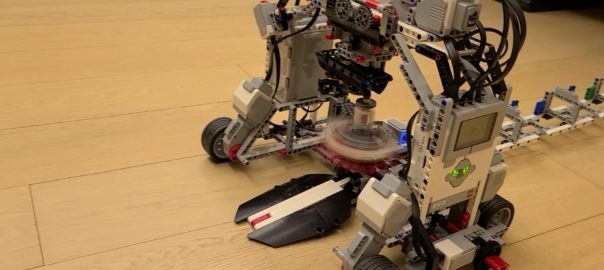
Features of the factory
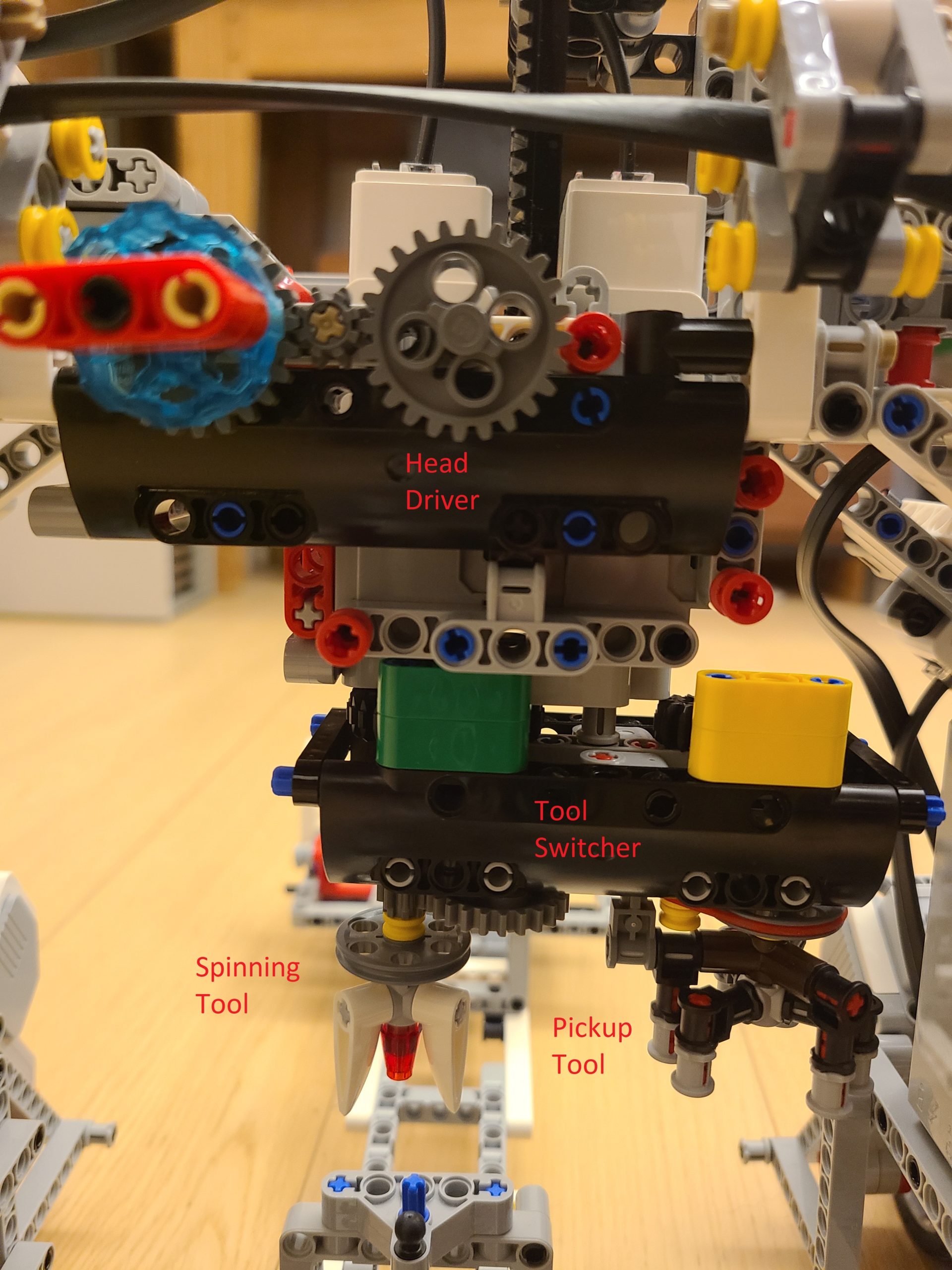
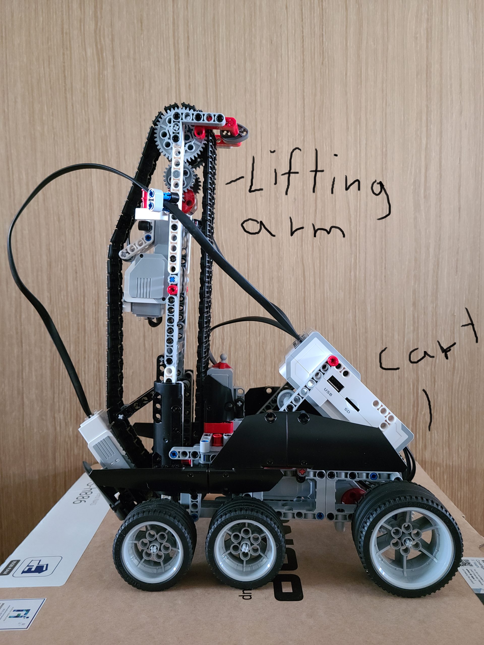
Head control – The first function is moving the head up and down getting the spinner parts. The second function is switching the tool for the head, one is to pickup the spinner parts and place it on the spinner holder, the other one is the spinning tool which will spin the finished product.
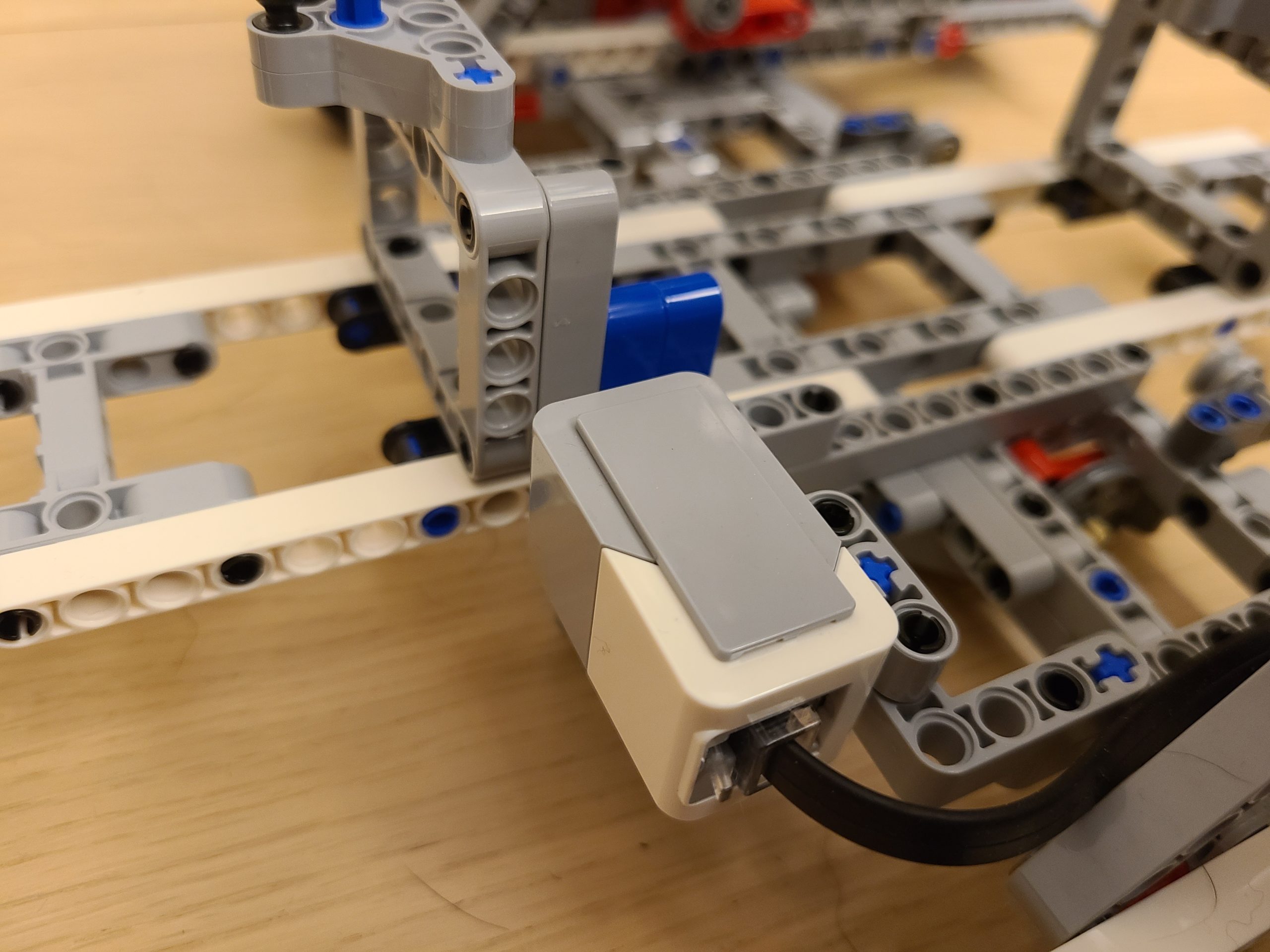
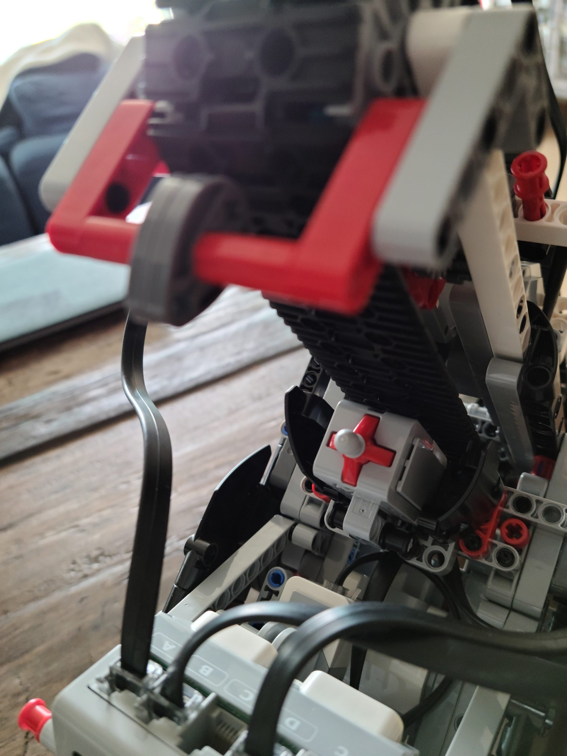
Color Sensor – This Color sensor is used for detecting the color, so that we can make the bridge go in the sequence you picked. For example, if you pick blue, green, yellow, and red, then the bridge will go in the order you have picked. We have also changed the color tags location, so that it will be easier to program the movement part and pickup the spinner part right at the spot where the bridge stops. The original design by LEGO will make it harder because you have to calculate how far the bridge need to travel after detecting the color tag. But, it is easier for operator to identify the part position.
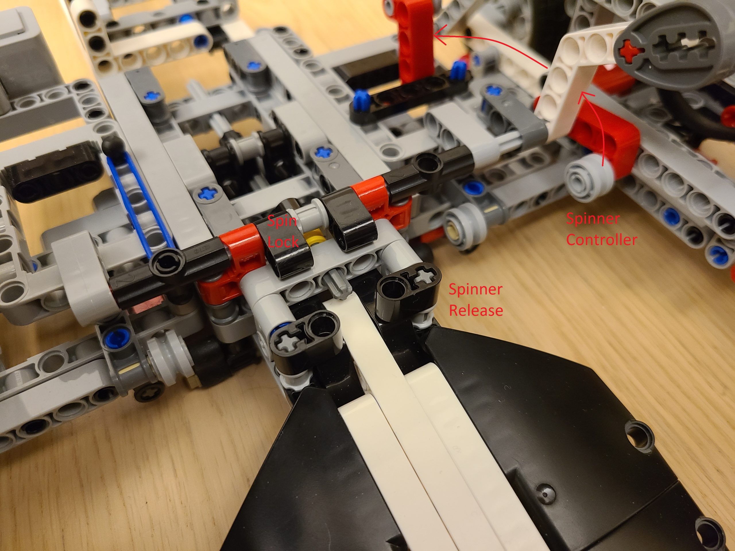
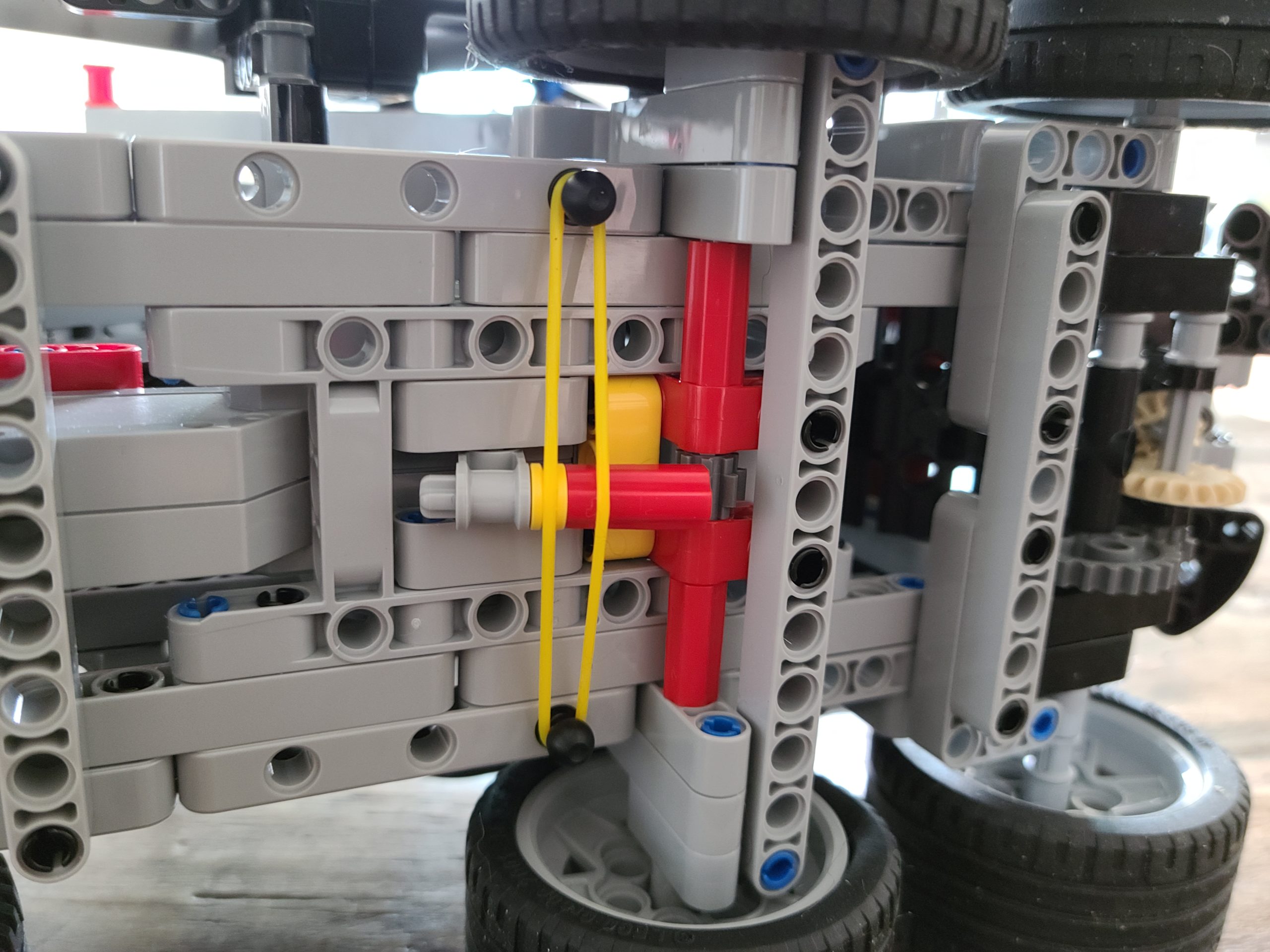
Spinner control – This is used to release the spinner after it was spun and it also controls the spin lock which lets the spinner lock it in place prior it can be spun. It works by using the motor to turn the red handle up to unlock the spin lock and let it spin. The second step is turning the handle to it’s maximum to release the spinner after it is spun.
However, we made some improvement by moving the bridge ahead to push the handle to maximum instead of using the spinner control. So that the spinner will not hit the the bridge wheels.
Calibration
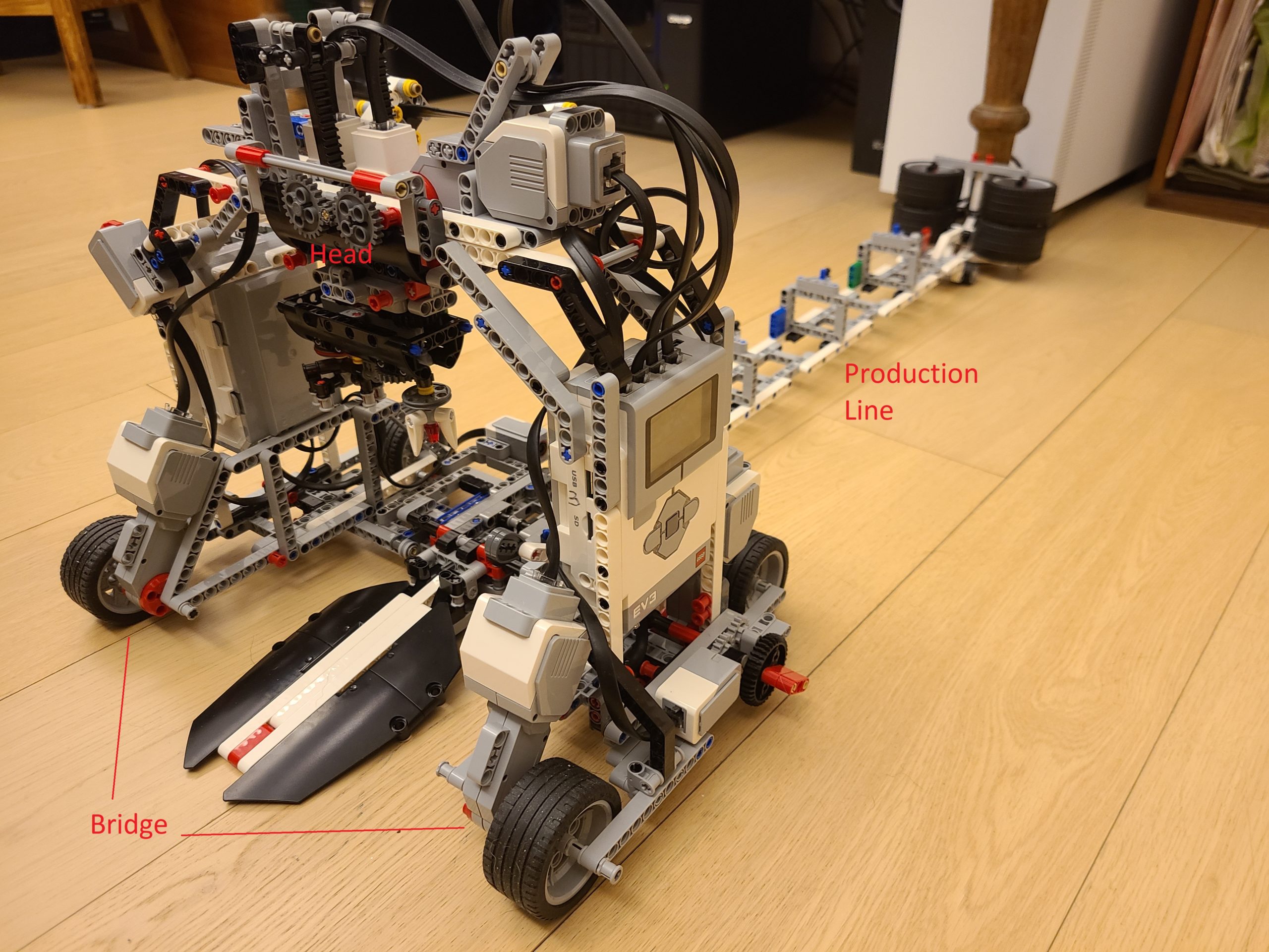
The Bridge
def bridge_position():
    bridge_move(-180)

    while True:
        if rail_color_detect() == 1:
            bridge_move(0)
            ev3.speaker.beep()
            ev3.speaker.beep()
            break
    bridge_move(180) # Prepare a position to call for head calibration
    wait(600)
    bridge_move(0)
    mbox.send('Calibration')
    mbox.wait()
    bridge_move(-180)
    while True:
        if rail_color_detect() == 1:
            bridge_move(0)
            ev3.speaker.beep()
            ev3.speaker.beep()
            break
The Head
def calibration():
    # Height Control Calibration, max. drive = -526, best pickup position = -490
    height_control.dc(10)
    height_control.run_until_stalled(500,Stop.HOLD,50)
    height_control.reset_angle(0)

    # Switch tool : 200 is spinning tool 0 is pickup tool
    # Use 300 to hold the spinner, -300 to release, i.e. pickup tool
    switch_tools.run_until_stalled(-100,Stop.HOLD)
    spinning_tool.run_angle(500,-300,Stop.HOLD)
In the bridge program we made the bridge go back to the first color which is white (we added white ourselves), when the color sensor detects white, it will stop the bridge and move half a step forward whilst communicating with another program that controls the head. When the head received a message saying “calibration” the program will call the calibration program that we have defined as a function. In the function “calibration” we made the height of the head reset to the max which we made it go up to the top, after resetting the height of the head, we switched the tool back to the pickup tool, then we reset the pickup tool by opening the claw so that it can pick up the spinner. Then, the bridge will return the zero position, i.e. the white tag.
How does the program work?
It is not difficult to create the program from moving the bridge, control the head. However, it took us hours to fine tune all the parameters and settings.
Communication
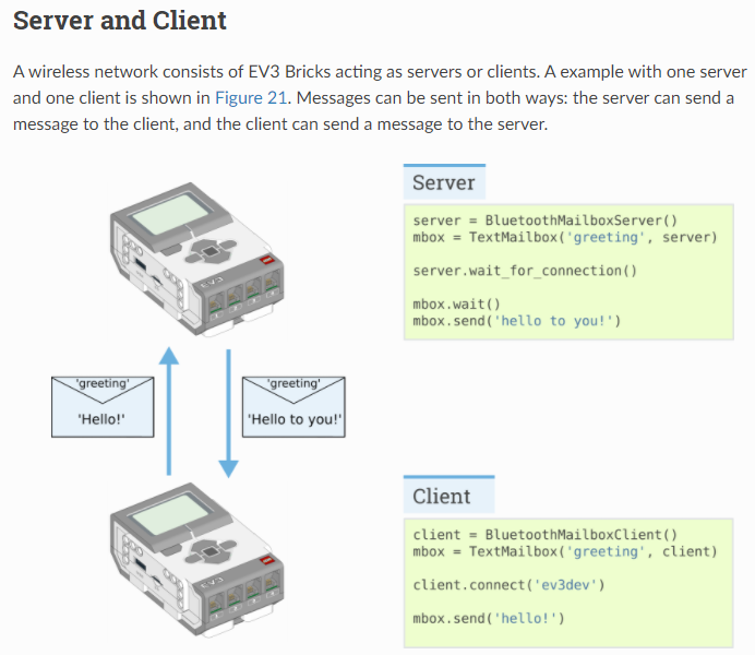
Since this factory using two EV3 Bricks. Using EV3-G (LabView) can support Daisy Chain, i.e. one program to control multiple devices. However, we don’t want to deal with EV3-G anymore and EV3 Classroom just support one device. So, we go for EV3DEV, we pair two EV3 Bricks via Bluetooth and communicate by messaging each others. You can refer to these link for EV3DEV Bluetooth messaging.
Color Detection
# Define the functions
def rail_color_detect():# 1 - White, 2 - Yellow, 3 - Blue, 4 - Green, 5 - Red, 0 - unstable, 99 - others
    for i in range(0,300):
        if i == 0:
            first_color = rail_detector.color()
        if rail_detector.color() != first_color:
            return 0
    if first_color == Color.WHITE:
        return 1
    if first_color == Color.YELLOW:
        return 2
    if first_color == Color.BLUE:
        return 3
    if first_color == Color.GREEN:
        return 4
    if first_color == Color.RED:
        return 5
    return 99
When we developed the program, we found that LEGO color sensor is running unstable, it would provide incorrect color (i.e. noise) occasionally and make our program actioning wrongly. To fix the color sensor misjudgment, we created a color detect function to detect the color 300 times. If all 300 detections are the same, then we can confirm the color detect correctly and return the color code – 1. White, 2. Yellow, 3. Blue, 4. Green and 5. Red. For wrong color detect, it will be 0. 99 for others.
The Bridge
# Start of the main program
ev3.speaker.beep()
bridge_position()

ev3.speaker.set_volume(100)
ev3.speaker.say("Scan the color now")
color_seq = []
color_selection()

ev3.speaker.beep()

for i in range(0,4):
    bridge_move(180)

    while True:
        if rail_color_detect() == color_seq[i]:
            bridge_move(0)
            mbox.send('Pickup')
            mbox.wait()

            bridge_move(-180)
            while True:
                if rail_color_detect() == 1:
                    bridge_move(0)
                    break

            mbox.send('Release')
            mbox.wait()
            break

mbox.send('Spin')
mbox.wait()
bridge_move(1500)
wait(1000)
bridge_move(0)
mbox.send('All Done')
In this program we reset the bridge to the starting point at “the white tag”, then we scan the color sequence that we want to pickup the spinner part in. The next part we make the bridge go to the color tag in the sequence, then call the head to pickup the spinner part. After it picks up the spinner part, the head will send a message back to the bridge and it will go back to the first tag “white” and again calls the head to releases the spinner part. These steps will be repeated until last part is placed.
The Head
while True:
    mbox.wait()
    message = mbox.read()
    if message == 'Calibration':
        calibration()
    if message == 'Pickup':
        pickup_parts()
    if message == 'Release':
        release_parts()
    if message == 'Spin':
        spin_spinner()
    if message == 'All Done':
        break
    mbox.send('Done')
The head receive a message from the bridge, if the message matches one of the defined message, it will do the corresponding function, such as Pickup – pickup the spinner part. Once the action is done, a message ‘Done’ will send back to the head to confirm that it’s finished.
Pickup Part
def pickup_parts():
    height_control.run_angle(500,-460)
    spinning_tool.run_angle(1000,300,Stop.HOLD)
    height_control.run_angle(500,460)
That’s pretty simple, makes the head go down, pickup the spinner, then go up.
Release Part
def release_parts():
    height_control.run_angle(500,-150)
    spinning_tool.stop()
    wait(300)
    switch_tools.run_angle(500,20,Stop.HOLD,wait=True)
    spinning_tool.run_angle(500,-300)
    switch_tools.run_angle(500,-20)
    height_control.run_angle(500,150)
In this function we made the head go down, adjust the pickup tool angle, release the part , then go up. Why do we need to adjust the tool angle? It is because when the bridge moves on the rail, the vibration will tilt the spinner holder a bit and causing the positioning to be wrong for the part placement, so we adjust the tool angle to compensate this.
Start the spinner and release it
def spin_spinner():
    switch_tools.run_until_stalled(1000)
    switch_tools.hold()
    height_control.run_angle(50,-130,Stop.HOLD,wait=False)

    for i in range(0,6):
        spinning_tool.run_angle(100,-30)
        spinning_tool.run_angle(100, 30)

    release_tool.run_angle(500,170)
    switch_tools.stop()
    spinning_tool.dc(-100) # Must rotate in Clockwise Direction, otherwise the head will be mis-aligned
    wait(5000)
    height_control.run_angle(1500,130,Stop.HOLD,wait=True)
    # release_tool.run_angle(1500,60)
    mbox.send('Move!')
    spinning_tool.dc(0)
It switch the tool switcher to the spinning tool. Then we make the head go down to a height that is considerable for the spinner to spin perfectly. While the head goes down the spinning tool will turn left & right for 10 times ( this is for locking in the angle so we get a better spinning angle). After the spinning tool locks on the spinner, it will spin in 1500 rotation per seconds for 5 seconds, then the bridge will move back quickly. When the bridge move back it will trigger the spinner controller to release the spinner. Originally, the spinner controller should be trigger by the handle. However, the spinner will hit the bridge wheel and failed the mission. So, we move the bridge front to avoid it.
Build instruction and the program
We created the program from scratch without referring any example, you can download from below.
LEGO official build instruction