Category Archives: Features Projects

Drone Programming – Gesture Control

Once I did the face detection project, it made me easier to understand gesture recognition, you can do it too. It gives me more solid fundamentals to start with deep learning studying, I want to create my objection recognition model and have the drone fly with this. Before that, I like to try body detection and swap fly as my next project. OK, let’s see how we make this happen in our drone.

Basic Concept

  • Capture video frame from the drone
  • Use a hand detection tool to identify hands from the frame and identify the left hand.
  • Based on the hand-detected information (including wrist, finger, knuckles & phalanges) and the logic, we will achieve gesture control.

Understanding your hand

First of all, let’s understand our hands first… XD

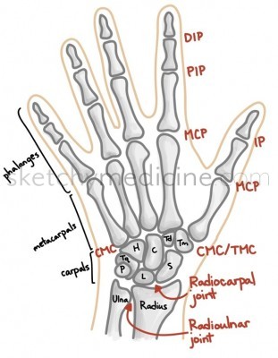
I got this picture from sketchymedicine.com, it contains a lot of medical sketches and detailed information, very cool website.

Program with MediaPipe

See below for the full program

from djitellopy import Tello
import cv2
import mediapipe as mp
import threading
import math
import logging
import time

# Assign tello to the Tello class and set the information to error only
tello = Tello()
tello.LOGGER.setLevel(logging.ERROR) #Ignore INFO from Tello
fly = False #For debuggin purpose

# Assign the MediaPipe hands detection solution to mpHands and define the confidence level
mpHands = mp.solutions.hands
hands = mpHands.Hands(min_detection_confidence=0.8, min_tracking_confidence=0.8)

# When we detect the hand, we can use mp.solution to plot the location and connection
mpDraw = mp.solutions.drawing_utils

def hand_detection(tello):

    while True:
        
        global gesture
        
        # Read the frame from Tello
        frame = tello.get_frame_read().frame
        frame = cv2.flip(frame, 1)
        
        # Call hands from MediaPipe Solution for the hand detction, need to ensure the frame is RGB
        result = hands.process(frame)
        
        # Read frame width & height instead of using fixed number 960 & 720
        frame_height = frame.shape[0]
        frame_width = frame.shape[1]
        my_hand = []
        
        if result.multi_hand_landmarks:
            for handlms, handside in zip(result.multi_hand_landmarks, result.multi_handedness):
                if handside.classification[0].label == 'Right': # We will skip the right hand information
                    continue
                        
                # With mp.solutions.drawing_utils, plot the landmark location and connect them with define style        
                mpDraw.draw_landmarks(frame, handlms, mpHands.HAND_CONNECTIONS,\
                                        mp.solutions.drawing_styles.get_default_hand_landmarks_style(),\
                                        mp.solutions.drawing_styles.get_default_hand_connections_style())          
               
                # Convert all the hand information from a ratio into actual position according to the frame size.
                for i, landmark in enumerate(handlms.landmark):
                    x = int(landmark.x * frame_width)
                    y = int(landmark.y * frame_height)
                    my_hand.append((x, y))
                                        
                # Capture all the landmarks position and distance into hand[]
                # wrist = 0       
                # thumb = 1 - 4
                # index = 5 - 8
                # middle = 9 - 12
                # ring = 13 - 16
                # little = 17 - 20
                
                # Setup left hand control with the pre-defined logic. 
                # Besides thumb, we use finger tip y position compare with knuckle y position as an indicator
                # Thumb use the x position as the comparison.
                
                # Stop, a fist
                # Land, open hand
                # Right, only thumb open
                # Left, only little finger open
                # Up, only index finger open
                # Down, both thumb and index finger open
                # Come, both index and middle fingger open
                # Away, both index, middle and ring finger open            
                finger_on = []
                if my_hand[4][0] > my_hand[2][0]:
                    finger_on.append(1)                     
                else:
                    finger_on.append(0) 
                for i in range(1,5):
                    if my_hand[4 + i*4][1] < my_hand[2 + i*4][1]: 
                        finger_on.append(1)
                    else:
                        finger_on.append(0)
                
                gesture = 'Unknown'        
                if sum(finger_on) == 0:
                    gesture = 'Stop'
                elif sum(finger_on) == 5:
                    gesture = 'Land'
                elif sum(finger_on) == 1:
                    if finger_on[0] == 1:
                        gesture = 'Right'
                    elif finger_on[4] == 1:
                        gesture = 'Left'
                    elif finger_on[1] == 1:
                        gesture = 'Up'
                elif sum(finger_on) == 2:
                    if finger_on[0] == finger_on[1] == 1:
                        gesture = 'Down'
                    elif finger_on[1] == finger_on[2] == 1:
                        gesture = 'Come'
                elif sum(finger_on) == 3 and finger_on[1] == finger_on[2] == finger_on[3] == 1:
                    gesture = 'Away'
                
        cv2.putText(frame, gesture, (10, 50), cv2.FONT_HERSHEY_SIMPLEX, 2, (255, 0, 0), 3)
        frame = cv2.cvtColor(frame, cv2.COLOR_BGR2RGB) 
        cv2.imshow('Tello Video Stream', frame)
        cv2.waitKey(1)
        if gesture == 'Landed':
            break      

########################
# Start of the program #
########################

# Connect to the drone via WIFI
tello.connect()

# Instrust Tello to start video stream and ensure first frame read
tello.streamon()

while True:
            frame = tello.get_frame_read().frame
            if frame is not None:
                break

# Start the hand detection thread when the drone is flying
gesture = 'Unknown'
video_thread = threading.Thread(target=hand_detection, args=(tello,), daemon=True)
video_thread.start()    

# Take off the drone
time.sleep(1)
if fly:
    tello.takeoff()
    tello.set_speed(10)
    time.sleep(2)
    tello.move_up(80)
    
while True:
    
    hV = dV = vV = rV = 0
    if gesture == 'Land':
        break
    elif gesture == 'Stop' or gesture == 'Unknown':
        hV = dV = vV = rV = 0
    elif gesture == 'Right':
        hV = -15
    elif gesture == 'Left':
        hV = 15
    elif gesture == 'Up':
        vV = 20
    elif gesture == 'Down':
        vV = -20
    elif gesture == 'Come':
        dV = 15
    elif gesture == 'Away':
        dV = -15
        
    tello.send_rc_control(hV, dV, vV, rV)

    
# Landing the drone
if fly: tello.land()
gesture = 'Landed'

# Stop the video stream
tello.streamoff()

# Show the battery level before ending the program
print("Battery :", tello.get_battery())
    
Python

Hand Detection

# Assign the MediaPipe hands detection solution to mpHands and define the confidence level
mpHands = mp.solutions.hands
hands = mpHands.Hands(min_detection_confidence=0.8, min_tracking_confidence=0.8)
Python

From MediaPipe, we are going to use MediaPipe Solution Hands for our hand detection, there are a few parameters that are important to us,

  • min_hand_detection_confidence – that’s the first step to identifying a hand in the single frame. At which score of detection is considered a success, the lower the number, the more detected objects can pass but the higher the chance of error. The higher the number, need a very high the score object, i.e. a very clear and precise hand image.
  • min_tracking_confidence – Once the hand is detected based on the min_hand_detection_confidence requirement, it will do the hand tracking with this number.

You can refer to the MediaPipe Official Website for more information. They also get a demonstration website for you to play with different models. However,

  def __init__(self,
               static_image_mode=False,
               max_num_hands=2,
               model_complexity=1,
               min_detection_confidence=0.5,
               min_tracking_confidence=0.5):
Python

I found that the documentation on the MediaPipe Official Website may not be updated, and min_hand_presence_confidence and running_mode no longer exist. What I checked from hands.py. It spent me 30 minutes playing with the demo and reading information to understand the difference between min_hand_detection_confidence and min_hand_presence_confidence.

gesture = 'Unknown'
video_thread = threading.Thread(target=hand_detection, args=(tello,), daemon=True)
video_thread.start()    
Python

Just like what we did in face detection, we need to run the hand detection function in a thread (parallel processing) to capture and analyze the hand position, updating a global variable – gesture, so that the drone movement control can take corresponding actions according to this.

# Read the frame from Tello
        frame = tello.get_frame_read().frame
        frame = cv2.flip(frame, 1)
        
        # Call hands from MediaPipe Solution for the hand detction, need to ensure the frame is RGB
        result = hands.process(frame)
Python

Get the latest frame from the drone and flip it from the camera point of view to our point of view. Then, process the frame with hands, it was predefined in the beginning – line #11. Once the hand detection is done, the following information will be stored in result, it will contain,

  • result.multi_handedness – ‘Left’ or ‘Right’ hand
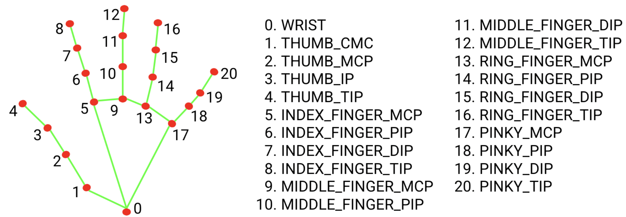
  • result.multi_hand_landmarks – an array containing 21 sets of data as show below, they call it landmarks, each landmark including the x, y & z position. But, the x and y coordinates are normalized to [0.0, 1.0] by the image width and height, respectively. The z coordinate represents the landmark depth, with the depth at the wrist being the origin.
  • result.multi_hand_world_landmarks – The 21 hand landmarks are also presented in world coordinates. Each landmark is composed of xy, and z, representing real-world 3D coordinates in meters with the origin at the hand’s geometric center.
        if result.multi_hand_landmarks:
            for handlms, handside in zip(result.multi_hand_landmarks, result.multi_handedness):
                if handside.classification[0].label == 'Right': # We will skip the right hand information
                    continue
Python

If hand(s) are detected, the result will contain the necessary data. Since we only need to use the left hand to control the drone, we will skip reading the Right hand data.

mpDraw = mp.solutions.drawing_utils
Python
                mpDraw.draw_landmarks(frame, handlms, mpHands.HAND_CONNECTIONS, mp.solutions.drawing_styles.get_default_hand_landmarks_style(), mp.solutions.drawing_styles.get_default_hand_connections_style())                            
Python

Then, we use the drawing_utils from MediaPipe to highlight the landmarks and connect them.

                # Convert all the hand information from a ratio into actual position according to the frame size.
                for i, landmark in enumerate(handlms.landmark):
                    x = int(landmark.x * frame_width)
                    y = int(landmark.y * frame_height)
                    my_hand.append((x, y))   
Python

Retreves result.multi_hand_landmarks x & y data and converts this into actual position to the frame size. Store into array my_hand for the gesture analysis.

Logic for different gestures – Finger open or close?

We just simply compare the y position of the fingertip (TIP) to the knuckle (MCP). For the thumb, we compare the x position of the fingertip (TIP) to the knuckle (MCP) as shown below,

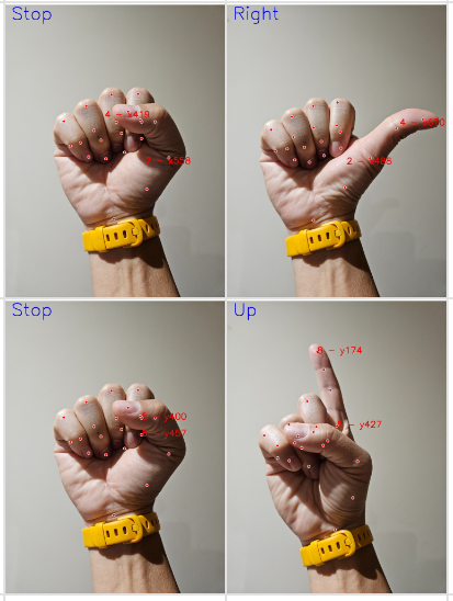
When thumb is open, finger tip x is bigger then knuckle x. When the fingers are open, finger tip y is smaller than knuckle y.

                finger_on = []
                if my_hand[4][1] > my_hand[2][1]:
                    finger_on.append(1)                     
                else:
                    finger_on.append(0) 
                for i in range(1,5):
                    if my_hand[4 + i*4][3] > my_hand[2 + i*4][3]: 
                        finger_on.append(1)
                    else:
                        finger_on.append(0)
                
                gesture = 'Unknown'        
                if sum(finger_on) == 0:
                    gesture = 'Stop'
                elif sum(finger_on) == 5:
                    gesture = 'land'
                elif sum(finger_on) == 1:
                    if finger_on[0] == 1:
                        gesture = 'Right'
                    elif finger_on[4] == 1:
                        gesture = 'Left'
                    elif finger_on[1] == 1:
                        gesture = 'Up'
                elif sum(finger_on) == 2:
                    if finger_on[0] == finger_on[1] == 1:
                        gesture = 'Down'
                    elif finger_on[1] == finger_on[2] == 1:
                        gesture = 'Come'
                elif sum(finger_on) == 3 and finger_on[1] == finger_on[2] == finger_on[3] == 1:
                    gesture = 'Away'
Python

We compare each fingers one by one and record into array finger_on, 1 represent open and 0 represent to close. By mapping this to our target gesture,

  • Left – finger_on = [0, 0, 0, 0, 1]
  • Right – finger_on = [1, 0, 0, 0, 0]
  • Up – finger_on = [0, 1, 0, 0, 0]
  • Down – finger_on = [1, 1, 0, 0, 0]
  • Come – finger_on = [0, 1, 1, 0, 0]
  • Away – finger_on = [0, 1, 1, 1, 0]
  • Stop – finger_on = [0, 0, 0, 0, 0]
  • Land – finger_on = [1, 1, 1, 1, 1]

Then, we use if/then loops to determinate variable gesture according to the finger_on result.

It may be fun if we use binary numbers to represent the above gesture determination.

Drone Movement Control

while True:
    
    hV = dV = vV = rV = 0
    if gesture == 'Land':
        break
    elif gesture == 'Stop' or gesture == 'Unknown':
        hV = dV = vV = rV = 0
    elif gesture == 'Right':
        hV = -15
    elif gesture == 'Left':
        hV = 15
    elif gesture == 'Up':
        vV = 20
    elif gesture == 'Down':
        vV = -20
    elif gesture == 'Come':
        dV = 15
    elif gesture == 'Away':
        dV = -15
        
    tello.send_rc_control(hV, dV, vV, rV)
Python

With the real-time global variable gesture from the hand_detection(), we use this variable to command the drone movement, with the SEND_RC_CONTROL command.

Horizontal-100 – 0 to move left0 – 100 to move right
Depth -100 – 0 to move backward0 – 100 to move forward
Vertial-100 – 0 to move down0 -100 to move up
Rotation-100 – 0 to rotate anti-clockwsie 0 – 100 to rotate clockwise
SEND_RC_CONTROL(Horizontal velocity, Depth velocity, Vertial velocity, Rotation velocity)

Unlike the Face Detection project, we used hV to control the Left and Right movement instead of rotation- rV. Oh.. the ‘Left/Right’ in the program is from the user’s point of view, but the drone camera view, is reversed.

That’s all for the project. It is quite straightforward and similar to the Face Detection. Please leave a comment for any inputs and comment. I am now studying how to do swarm flying with 3 Tello Edu, just cleaned up some roadblockers…

New Command – Follow

Just pop-up that I can add a ‘follow’ command, like what was doing for the face detection and tracking. I believe that we just need to copy & paste the code from the Face Detection project with some modifications.

Above is the hand sign for ‘follow’, go ahead to modify the original code with belows,

        global gesture
        global hand_center # New line for hand follow
Python
                # New line for hand follow    
                elif sum(finger_on) == 3 and finger_on[0] == finger_on[1] == finger_on[2] == 1:
                    gesture = 'Follow'
                    
                    #Apply Shoelace formula to calculate the palm size
                    palm_vertexs = [0,1,2,5,9,13,17]
                    area = 0                    
                    for i in palm_vertexs:
                        x1, y1 = my_hand[i]
                        x2, y2 = my_hand[(i + 1) % 7]
                        area += (x1 * y2) - (x2 * y1)
                    area = 0.5 * abs(area)
                    
                    hand_center = my_hand[0][0], my_hand[0][1], area
Python
gesture = 'Unknown'
hand_center = 480, 360, 28000 # New line for hand follow
Python
    # New line for hand follow
    elif gesture == 'Follow':
        x, y, size = hand_center
    
        if x > 480:
            rV = -int((x - 480)/4.8)            
        elif x < 480:
            rV = +int((480 - x)/4.8)
        else:
            rV = 0
        
        if y > 360: 
            vV = -int((y - 360)/3.6)
        elif y < 360: 
            vV = int((360 - y)/3.6)
        else:
            vV = 0
            
        if size > 30000:
            dV = -15
        elif size < 26000:
            dV = 15
        else:
            dV = 0            
            
    tello.send_rc_control(hV, dV, vV, rV)
Python

That’s all!

Shoelace Formula

For the above codes, we use landmarks – 0, 1, 2, 5, 9, 13 & 17 to calculate the area of the palm, and this number determines how close the palm is to the drone, we target a range of 26000 – 30000. Then, we command it to fly toward or away from the hand, just similar to the face tracking in the last project.

But, what I want to highlight is the palm area calculation, it led me to learn about the Shoelace Formula, which is a very interesting and powerful formula. I don’t remember that I learned this before, maybe returned this to my teacher already 😎. Anyway, have a look at the below video, it’s worth watching and understanding the Shoelace Formula.

Drone Programming – Face Detection and Tracking

If I hadn’t tried, I never have known that doing face detection nowadays is such simple and easy. Even for a beginner like me, I can make it happen within a few hours… after I spent a few days learning and understanding the libraries. It is worth having a try, it will lead you to a new world and start to understand vision computing, deep learning, and AI development. Let’s take a look at what I did.

Basic Concept

  • Capture video frame from the drone
  • Use a face detection tool to identify the main face from the frame. Since we have not yet applied face recognition, we just picked the closet one as the main face.
  • Based on the face detected position (x, y) to move the drone and make the face at the center of the frame.

Program with CV2 model

See below for the full program

# Before you run this program, ensure to connect Tello with the WIFI

# Import Tello class from djitellopy library
from djitellopy import Tello

# Import additional library CV2 - OpenCV for image processing, threading for multi-tasking
import cv2
import threading
import time
import logging

# Assign tello to the Tello class and set the information to error only
tello = Tello()
tello.LOGGER.setLevel(logging.ERROR) #Ignore INFO from Tello
fly = True #For debuggin purpose

# Assign the pre-trained model - Haar Cascade classifier for CV2 face detection
face_cascade = cv2.CascadeClassifier(cv2.data.haarcascades + 'haarcascade_frontalface_default.xml')
eyes_cascade = cv2.CascadeClassifier(cv2.data.haarcascades + 'haarcascade_eye.xml') 

# def a video capture and display function
def face_detection(tello):

    while True:
        # Change the face_center to be global, any changes will be read globally
        global face_center
                
        # Read the frame from Tello and convert the color from BGR to RGB
        frame = tello.get_frame_read().frame
        frame = cv2.cvtColor(frame, cv2.COLOR_BGR2RGB)
        
        # Convert the image to grayscale for face detection
        gray = cv2.cvtColor(frame, cv2.COLOR_RGB2GRAY)

        # Perform face detection using the pre-train model - haarcascade_frontalface_default.xml
        faces = face_cascade.detectMultiScale(gray, scaleFactor=1.05, minNeighbors=10, minSize=(80, 80))
        
        
        # Based on CV2 result, find the largest detected face and the position    
        largest_area = 0
        largest_face = None
                
        for (x, y, w, h) in faces:
            face_area = w * h
            if face_area > largest_area:
                largest_area = face_area
                largest_face = (x, y, w, h)
        
        # Confirm there are two eyes detected inside the face           
        if largest_face is not None:
            eyes = eyes_cascade.detectMultiScale(gray) # Using the default parameters
            eye_count = 0
            for (ex, ey, _, _) in eyes:
                if ex - x < w and ey - y < h:
                    eye_count += 1
            if eye_count < 2:
                continue
            
        # Highlight the largest face with a box and show the coordinates             
            x, y, w, h = largest_face
            face_center = (x + w/2), (y + h/2), w
            cv2.rectangle(frame, (x, y), (x+w, y+h), (255, 0, 0), 2)
            position_text = f'Face : (x :{x}, y :{y}, w :{w}, h :{h})'
            center_text = f'{int(x + w/2)} , {int(y + h/2)}'
            rc_text = f'RC({hV}, {dV}, {vV}, {rV})'
            cv2.putText(frame, position_text, (x, y-10), cv2.FONT_HERSHEY_SIMPLEX, 0.5, (255, 0, 0), 2)
            cv2.putText(frame, center_text, (int(x + w/2), int(y + h/2)), cv2.FONT_HERSHEY_SIMPLEX, 0.5, (255, 0, 0), 2)
            cv2.putText(frame, rc_text, (20, 20), cv2.FONT_HERSHEY_SIMPLEX, 0.5, (0, 255, 0), 2)
        else:
            face_center = 480, 360, 200
        
        # Display the face detected image and check whether 'q' is bing pressed or not
        cv2.imshow('Tello Video Stream', frame)              
        if cv2.waitKey(1) & 0xFF == ord('q'):
            face_center = False
            break

########################
# Start of the program #
########################

# Connect to the drone via WIFI
tello.connect()

# Instrust Tello to start video stream and ensure first frame read
tello.streamon()

while True:
            frame = tello.get_frame_read().frame
            if frame is not None:
                break

# Start the face detection thread when the drone is flying
face_center = 480, 360, 200
hV = vV = dV = rV = 0
video_thread = threading.Thread(target=face_detection, args=(tello,), daemon=True)
video_thread.start()

# Take off the drone
time.sleep(1)
if fly:
    tello.takeoff()
    tello.set_speed(10)
    time.sleep(2)
    tello.move_up(80)

# Use RC Control to control the movement of the drone
# send_rc_control(left_right_velocity, forward_backward_velocity, up_down_velocity, yaw_velocity) from -100 to 100

while face_center != False:
    
    x, y, w = face_center

    if x > 530:
        rV = +30           
    elif x < 430:
        rV = -30
    else:
        rV = 0
    
    if y > 410: 
        vV = -20 
    elif y < 310: 
        vV = 20 
    else:
        vV = 0
        
    if w > 300:
        dV = -15
    elif w < 200:
        dV = 15
    else:
        dV = 0
    
    tello.send_rc_control(hV, dV, vV, rV)
      
# Landing the drone
if fly: tello.land()

# Stop the video stream
tello.streamoff()

# Show the battery level before ending the program
print("Battery :", tello.get_battery())
Python

If you installed the DJITELLOPY package, CV2 is being installed as well. Otherwise, you need to do this with – PIP install djitellpy.

Face Detection

face_cascade = cv2.CascadeClassifier(cv2.data.haarcascades + 'haarcascade_frontalface_default.xml')
Python

Besides face detection, CV2 provides different models to support different purposes. All of them are already downloaded when you install the CV2 package. For face detection, we use haarcascade_frontalface_default.xml.

face_center = 480, 360, 200
hV = vV = dV = rV = 0
video_thread = threading.Thread(target=face_detection, args=(tello,), daemon=True)
video_thread.start()
Python

The program structure is very similar to the video-capturing project. We need to run the face detection function in a thread (parallel processing) to capture and analyze the face position, updating a global variable – face_center, so that the drone movement control can take corresponding actions.

        frame = tello.get_frame_read().frame
        frame = cv2.cvtColor(frame, cv2.COLOR_BGR2RGB)
        
        # Convert the image to grayscale for face detection
        gray = cv2.cvtColor(frame, cv2.COLOR_RGB2GRAY)

        # Perform face detection using the pre-train model - haarcascade_frontalface_default.xml
        faces = face_cascade.detectMultiScale(gray, scaleFactor=1.05, minNeighbors=10, minSize=(80, 80))
Python

Referring to the last project, we use get_frame_read() to get the latest frame from Tello’s camera. As we mentioned before, CV2 processes image data in BGR format but the image feed from Tello’s camera is in RGB format, the ‘R’ & ‘G’ are mis-mapped. We need to convert this into ‘RGB’ for a correct display. Then, we also need to create an image in grayscale because CV2 performs face detection in grayscale.

We use detectMultiScale to perform face detection based on the face_cascade setup and the grayscale image, the result will be stored in faces. There are three inputs to alter the detection result. Be short,

  • scaleFactor – controls the resizing of the image at each step to detect objects of different sizes. The higher the number, the faster the progress but more chance of missing faces.
  • minNeighbors – controls the sensitivity of the detector by requiring a certain number of overlapping detections to consider a region as a positive detection. Lower the number, more sensitive to potential detections, potentially resulting in more detections but also more false positives.
  • minSize – minimum size of the face detected, very straightforward
        largest_area = 0
        largest_face = None
                
        for (x, y, w, h) in faces:
            face_area = w * h
            if face_area > largest_area:
                largest_area = face_area
                largest_face = (x, y, w, h)
Python

Once the face detection is done, face position and sizes will be returned to the array variable faces, len of faces representing how many faces are detected and each faces[] contains the detected position x, position y, width, and height. We are using a for loop to read the x, y, w & h and identify the largest face as we mentioned before.

vvv Small tool to understanding Scale Factor and Min Neighbour vvv

# import the opencv library
import cv2
  
# Load the pre-trained Haar Cascade classifier for face detection
face_cascade = cv2.CascadeClassifier(cv2.data.haarcascades + 'haarcascade_frontalface_default.xml')
  
scale_factor = 1.1
min_neighbors = 10
      
while(True):
  
    frame = cv2.imread("people.jpg")
    
    # Convert the image to grayscale for face detection
    gray = cv2.cvtColor(frame, cv2.COLOR_BGR2GRAY)

    # Perform face detection
    faces = face_cascade.detectMultiScale(gray, scaleFactor=scale_factor, minNeighbors=min_neighbors, minSize=(100, 100))
    biggest_face = [0, 0, 0, 0]
    
    # Draw rectangles around the detected faces
    for i, (x, y, w, h) in enumerate(faces):
        cv2.rectangle(frame, (x, y), (x+w, y+h), (255, 0, 0), 2)
        position_text = f'Face {i+1}: (x :{x}, y :{y}, w :{w}, h :{h})'
        center_text = f'{int(x + w/2)} , {int(y + h/2)}'
        cv2.putText(frame, position_text, (x, y-10), cv2.FONT_HERSHEY_SIMPLEX, 0.5, (255, 0, 0), 2)
        cv2.putText(frame, center_text, (int(x + w/2), int(y + h/2)), cv2.FONT_HERSHEY_SIMPLEX, 0.5, (255, 0, 0), 2)
           
    cv2.putText(frame, f'scaleFactor = {scale_factor}, minNeighbors = {min_neighbors}', (10, 10), cv2.FONT_HERSHEY_SIMPLEX, 0.5, (0, 255, 0), 2)        
        
    # Display the resulting frame
    cv2.imshow('People', frame)
      
    # q - quit
    # a/s - add or reduce scale factor by 0.05
    # z/x - add or reduce min neighors by 1
    # desired button of your choice
    key = cv2.waitKey(0)
    if key == ord('q'):
        break
    elif key == ord('a') and scale_factor > 1.05:
        scale_factor = round(scale_factor - 0.05, 2)
    elif key == ord('s'):
        scale_factor = round(scale_factor + 0.05, 2)
    elif key == ord('z') and min_neighbors > 1:
        min_neighbors -= 1
    elif key == ord('x'):
        min_neighbors += 1
    
# Destroy all the windows
cv2.destroyAllWindows()
Python

To better understand the above parameters, I also wrote a small tool to alter Scale Factor (with a & s key) and Min Neighbour (with z & x key), you can have a try with different photos.

Eyes Detection

When we developed the program with face detection only, we found that there was a chance to have ‘fault detection’ no ever what parameters we tried, which would interfere with our result and induce a ‘ghost’ face. We had added eye detection to ensure a face with eyes is correctly detected, it can greatly improve the detection result.

eyes_cascade = cv2.CascadeClassifier(cv2.data.haarcascades + 'haarcascade_eye.xml') 
Python

Assigns haarcascade_eye.xml to eyes_cascade for eye detection.

        if largest_face is not None:
            eyes = eyes_cascade.detectMultiScale(gray) # Using the default parameters
            eye_count = 0
            for (ex, ey, _, _) in eyes:
                if ex - x < w and ey - y < h:
                    eye_count += 1
            if eye_count < 2:
                continue
Python

If the largest face is detected, we will do an eye detection to confirm the largest face with two eyes. Same as face detection, eye position, and size will be returned to the array of variable eyes. We need to compare that there are at least two eyes in the face box. Our logic is very simple, ensure that the eyes x & y position are within the face box, eye_x (ex) minus face_x (x) should be smaller than the width (w) and eye_y (ey) minus face_y (y) should be smaller than the height (h). Why at least two eyes? because it includes potential fault eye detection within the face box.

Face Position

        if largest_face is not None:
            eyes = eyes_cascade.detectMultiScale(gray) # Using the default parameters
            eye_count = 0
            for (ex, ey, _, _) in eyes:
                if ex - x < w and ey - y < h:
                    eye_count += 1
            if eye_count < 2:
                continue
            
        # Highlight the largest face with a box and show the coordinates             
            x, y, w, h = largest_face
            face_center = (x + w/2), (y + h/2), w
            cv2.rectangle(frame, (x, y), (x+w, y+h), (255, 0, 0), 2)
            position_text = f'Face : (x :{x}, y :{y}, w :{w}, h :{h})'
            center_text = f'{int(x + w/2)} , {int(y + h/2)}'
            rc_text = f'RC({hV}, {dV}, {vV}, {rV})'
            cv2.putText(frame, position_text, (x, y-10), cv2.FONT_HERSHEY_SIMPLEX, 0.5, (255, 0, 0), 2)
            cv2.putText(frame, center_text, (int(x + w/2), int(y + h/2)), cv2.FONT_HERSHEY_SIMPLEX, 0.5, (255, 0, 0), 2)
            cv2.putText(frame, rc_text, (20, 20), cv2.FONT_HERSHEY_SIMPLEX, 0.5, (0, 255, 0), 2)
        else:
            face_center = 480, 360, 200
Python

Once we confirm the largest face with eyes, we will get the face_center position ((x + w/2), (y + h/2)) and w for the drone movement. Since we are running the face_detection() in parallel, we make the face_center variable global, so that the drone can get the data in real-time and adjust the position. Then, we highlight the face with a blue box, the face position, and the drone movement (RC – we explain later) in the video for user information. If there is no face detected, the face_center will keep as 480, 360, 200.

Drone Movement Control

We target to position the largest face in the center of the camera. The resolution of Tello’s camera is 960 x 720, i.e. face center is (480, 360). It is not practical to position to a point, so we defined an area (480 +/- 50, 360 +/- 50).

With the real time face_center data from the face_detection(), we compare this with the box above.

  • if x > 530, we need to rotate the drone to right (view from the drone), i.e. clockwise
  • if x < 430, we need to rotate the drone to left (view from the drone, i.e anti-clockwise
  • if within the box, no movement is needed
  • if y > 410, we need to move up the drone
  • if y < 310, we need to move down the drone
  • if within the box, no movement is needed

Besides the x & y position, we also control how close the drone is to our face. We use the w (width) to make the judgment, we control the face size width between 300 – 200.

  • if w > 300, it too close, we need to move the drone away, i.e. backward
  • if w < 200, it too far, we need to move the drone closer, i.e. forward
  • if within the range, no movement is needed

DJITELLOPY SEND_RC_CONTROL

In our first project, we move the drone by using commands like move_up(), move_down(), rotate_clockwise(), etc.. Since this is a once-a-time command, the drone will be moving step by step, and also min. 20cm a time. The result will be lagging and unsmooth.

So, we use SEND_RC_CONTROL to control the drone movement. For RC_SEND_CONTROL, it can set the velocity of the drone in four dimensions a time.

* Left/Right is from drone’s view

Horizontal-100 – 0 to move left0 – 100 to move right
Depth -100 – 0 to move backward0 – 100 to move forward
Vertial-100 – 0 to move down0 -100 to move up
Rotation-100 – 0 to rotate anti-clockwsie 0 – 100 to rotate clockwise
SEND_RC_CONTROL(Horizontal velocity, Depth velocity, Vertial velocity, Rotation velocity)
# Use RC Control to control the movement of the drone
# send_rc_control(left_right_velocity, forward_backward_velocity, up_down_velocity, yaw_velocity) from -100 to 100

while face_center != False:
    
    x, y, w = face_center

    if x > 530:
        rV = +30           
    elif x < 430:
        rV = -30
    else:
        rV = 0
    
    if y > 410: 
        vV = -20 
    elif y < 310: 
        vV = 20 
    else:
        vV = 0
        
    if w > 300:
        dV = -15
    elif w < 200:
        dV = 15
    else:
        dV = 0
    
    tello.send_rc_control(hV, dV, vV, rV)
Python

As a result, we have the code above,

  • hV – Horizontal Velocity
  • dV – Depth Velocity
  • vV – Vertial Velocity
  • rV – Rotation Velocity

Since doing rotation is a better approach to adjusting the horizontal position, we used rV instead of hV. Once we send the velocity number to the drone, it will keep moving in the direction according to the velocity until the next change. So, the drone is flying smoothly to the face position and achieves face tracking.

That’s simple, right?

Face Detection with MediaPipe model?

Besides using CV2. haarcascade_frontalface_default.xml, we have tried to use the MediaPipe.blaze_face_short_range.tflite. We supposed the face detection good is better because it is a deep learning based model. And yes, it is better in accuracy and response. See below comparison,

However, blaze_face_short_range.tflite is a lightweight model for detecting single or multiple faces within selfie-like images from a smartphone camera or webcam. The model is optimized for front-facing phone camera images at short range. The result for our project is not ideal since it cannot detect a long-range face when I moved away from the drone, we will re-test this when the full-range blaze face is released.

See below for the full code with MediaPipe.

# Before you run this program, ensure to connect Tello with the WIFI

# Import Tello class from djitellopy library
from djitellopy import Tello

# Import additional library CV2 - OpenCV for image processing, threading for multi-tasking
# Import MediaPIPE for the face detection
import cv2
import threading
import time
import logging
import mediapipe as mp
from mediapipe.tasks import python
from mediapipe.tasks.python import vision

# Assign tello to the Tello class and set the information to error only
tello = Tello()
tello.LOGGER.setLevel(logging.ERROR) #Ignore INFO from Tello
fly = True #For debuggin purpose

# Upload the pre-trained model and setup the Face Detection Option for MediaPIPE
base_options = python.BaseOptions(model_asset_path='blaze_face_short_range.tflite')
options = vision.FaceDetectorOptions(base_options=base_options, min_detection_confidence = 0.8, min_suppression_threshold = 0.3)
detector = vision.FaceDetector.create_from_options(options)
  
# def a video capture and display function
def face_detection(tello):

    while True:
        # Change the face_center to be global, any changes will be read globally
        global face_center      
        
        # Read the frame from Tello and convert the color from BGR to RGB
        frame = tello.get_frame_read().frame
        frame = cv2.cvtColor(frame, cv2.COLOR_BGR2RGB)
        image = mp.Image(image_format = mp.ImageFormat.SRGB, data = frame)
        
        # Perform face detection using the pre-train model - blaze_face_short_range.tflite
        detection_result = detector.detect(image)
        
        # Based on the MediaPIPE result, find the largest detected face and the position    
        largest_area = 0
        largest_face = None
        
        #faces = len(face_position.detections)
        #if faces > 0:
        for face_position in detection_result.detections:
            x = face_position.bounding_box.origin_x
            y = face_position.bounding_box.origin_y
            w = face_position.bounding_box.width
            h = face_position.bounding_box.height
            face_area = w * h
            if face_area > largest_area:
                largest_area = face_area
                largest_face = (x, y, w, h)
        
        # Highlight the largest face with a box and show the coordinates        
        if largest_face is not None:
            x, y, w, h = largest_face
            face_center = (x + w/2), (y + h/2), w
            
            cv2.rectangle(frame, (x, y), (x+w, y+h), (255, 0, 0), 2)
            position_text = f'Face : (x :{x}, y :{y}, w :{w}, h :{h})'
            center_text = f'{int(x + w/2)} , {int(y + h/2)}'
            rc_text = f'RC({hV}, {dV}, {vV}, {rV})'
            cv2.putText(frame, position_text, (x, y-10), cv2.FONT_HERSHEY_SIMPLEX, 0.5, (255, 0, 0), 2)
            cv2.putText(frame, center_text, (int(x + w/2), int(y + h/2)), cv2.FONT_HERSHEY_SIMPLEX, 0.5, (255, 0, 0), 2)
            cv2.putText(frame, rc_text, (20, 20), cv2.FONT_HERSHEY_SIMPLEX, 0.5, (255, 0, 0), 2)
        else:
            face_center = 480, 360, 200
        
        # Display the face detected image and check whether 'q' is bing pressed or not
        cv2.imshow('Tello Video Stream', frame)              
        if cv2.waitKey(1) & 0xFF == ord('q'):
            face_center = False
            break

########################
# Start of the program #
########################

# Connect to the drone via WIFI
tello.connect()

# Instrust Tello to start video stream and ensure first frame read
tello.streamon()
while True:
            frame = tello.get_frame_read().frame
            if frame is not None:
                break

# Start the face detection thread when the drone is flying
face_center = 480, 360, 200
hV = vV = dV = rV = 0
video_thread = threading.Thread(target=face_detection, args=(tello,), daemon=True)
video_thread.start()

# Take off the drone
time.sleep(1)
if fly:
    tello.takeoff()
    tello.set_speed(10)
    time.sleep(2)
    tello.move_up(80)

# Use RC Control to control the movement of the drone
# send_rc_control(left_right_velocity, forward_backward_velocity, up_down_velocity, yaw_velocity) from -100 to 100
while face_center != False:
    
    x, y, w = face_center

    if x > 530:
        rV = +30           
    elif x < 430:
        rV = -30
    else:
        rV = 0
    
    if y > 410: 
        vV = -20 
    elif y < 310: 
        vV = 20 
    else:
        vV = 0
        
    if w > 250:
        dV = -15
    elif w < 150:
        dV = 15
    else:
        dV = 0
    
    tello.send_rc_control(hV, dV, vV, rV)
      
# Landing the drone
if fly: tello.land()

# Stop the video stream
tello.streamoff()

# Show the battery level before ending the program
print("Battery :", tello.get_battery())
Python

PID?

Thanks to Hacky from TelloPilots gave me the idea of PID, I started to study and am going to add this to the face detection project. To be frank, I got a failed mark and needed to redo the exam for the Feedback Control System when I was in college. However, I found it very important and useful when working… you may not know how useful what you were learning when you were a student. (sad..)

So, I need to do some revise first. See below for a basic PID concept,

As a result, I still have no clue how to implement PID into my program but change the speed from a constant value to a variable that varies according to the distance to the center. The result is much better and I can target the exact center (480,360) instead of a +/-50 box (480 +/- 50, 360 +/- 50), you can replace the following codes.

    if x > 480:
        rV = int((x - 480)/4.8)            
    elif x < 480:
        rV = -int((480 - x)/4.8)
    else:
        rV = 0
    
    if y > 360: 
        vV = -int((y - 360)/3.6)
    elif y < 360: 
        vV = int((360 - y)/3.6)
    else:
        vV = 0
Python

For safety reasons, I don’t implement this to the ‘Come’ and ‘Away’ speeds. I will keep studying how to implement the PID or you can give me an idea how to achieve this. Please leave me comment.

First Volunteer Teaching Class

We were so excited that we finished our first volunteer teaching class in our community, shared with a group of 6 kids aged 11 – 12. Introduced them to the world of Arduino by making simple LED circuity.

Thanks to LEARN CREATIVELY for the class arrangement.

I feel like I have learned a lot while teaching the students, I have learned how to teach people clearly and how to make them understand how to write the program and create the circuit. This lesson also proved that I can teach people programming and circuitry. I think I can have a better time management skill the next time I teach the kids. I want to have better time management skill because we didn’t have enough time to make other light patterns. – Alex

I have learnt a lot from this teaching experience. My programming skills may not be as good as Alex, but I was a good supporter. When Alex is teaching the class, I guided Alex to bring up different topics to make his teaching more fascinating. I also guided the students to have a better understanding of the program. From this teaching lesson, I have learnt that being a good supporter can help make big difference in how the students think and how the teacher speak. Because I forgot most of the programming techniques, so I took this lesson for granted and I managed to recover most of the techniques. Without this lesson, I don’t think I would even remember how to turn on a led. For this time’s lesson, I am very satisfied in the result, so I would like to continue teaching the kids or other kids! – Mountain

LEGO MindStorms – Znap with a remote controller

My dad told us that he wanted a RC car with a professional controller like this… that’s one of his childhood dream.

He was so excited with such professional controller we made…. HOWEVER, we built him this ‘car’… LOL

This is a great project to make use of two bricks and the messaging functions, how we connect the remote Controller with the Dog by feeding different data via different ‘mailbox’ is the key.

Features of the remote controller

Turning Wheel

The function of this wheel is to see how many degrees you turn the wheel. The more you turn the wheel, the higher number you get. If you turn it backwards, it will give you a negative number. Thus, positive number is turning right, negative number is turning left.

Direction Sensor

This is the Direction Sensor, this sensor detects how much you have tilted the handle. When you tilt the controller more forward, the higher number the sensor will give. If you tilt the controller backward, it will give you a negative number. Thus, positive number is going front, negative number is going back.

Calibration

The calibration is quite simple. When starts the program of the controller, just need to ensure the turning wheel back to 12’o clock position for easy control. Then, put the controller on a flat table to ensure the controller start from a horizontal position since we will use it’s tilting to control the ‘Dog’ direction.

Once all set, the program will reset the turning wheel angle and the direction sensor back to zero.

How does the program work?

Communication with different mail boxes

The Controller

SERVER = 'ev3dev2'
client = BluetoothMailboxClient()
client.connect(SERVER)

mbox = TextMailbox('Dog', client)
trigger_mbox = NumericMailbox('Trigger', client)
turn_mbox = NumericMailbox('Turn', client)
combo_mbox = LogicMailbox('Combo', client)
speed_mbox = NumericMailbox('Speed', client)

The Dog

server = BluetoothMailboxServer()
server.wait_for_connection()

mbox = TextMailbox('Dog', server)
trigger_mbox = NumericMailbox('Trigger', server)
turn_mbox = NumericMailbox('Turn', server)
combo_mbox = LogicMailbox('Combo', server)
speed_mbox = NumericMailbox('Speed', server)

These two programs connect two EV3 bricks via Bluetooth. We made different mailboxes to separate the communication between two bricks. For example, if we want to send information or message to tell the Dog how’s Turning Wheel result, it will be using mailbox ‘Turn’. So, we can perform very dedicate communication channels between the Controller and the Dog, make it easy way than using just one mailbox.

Messaging Synchronization

The Controller

# Sychronize the mail box between the robot and the remote
# Ensure the robot get new mail from the remote before start
# Once the robot get the new mail, will confirm Ready and OK to start
i = 0
while mbox.read() != 'Ready':
    trigger_mbox.send(i)
    turn_mbox.send(i)
    combo_mbox.send(i)
    speed_mbox.send(i)
    i = not i
combo_mbox.send(False)
mbox.send('OK')

The Dog

# Sychronize the mail box between the robot and the remote
# Ensure the robot get new mail from the remote before start
# Once the robot get the new mail, will confirm Ready and OK to start
trigger_mbox.wait_new()
turn_mbox.wait_new()
combo_mbox.wait_new()
speed_mbox.wait_new()
mbox.send('Ready')
mbox.wait()

Since we cannot ensure two bricks starting at the same time and same speed, we did a synchronization process to confirm two bricks ‘hand shake’ prior to start. We make the Dog mailboxes to read new mails only, it will wait until the Controller sends a new message to every mailboxes. Once new mails received, the Dog confirm ‘Ready’ and the Controller will reply by ‘OK’. Then, start the process.

It’s important. If the Dog runs faster, a ‘NONE’ message will be read because the Controller have not sent any messages yet. ‘NONE’ is not an value to be processed, which will induce an error.

We set ‘combo_mbox.send(False)’ because we don’t know the last message sent from the Controller is ‘1’ or ‘0’. If we don’t add this, it will result as a glitch that the Dog will randomly do Combo at start.

The Controller

while True:
    if mbox.read() == 'OK':
        
        combo_mbox.send(combo_sensor.pressed())
        turn_mbox.send(turn_sensor.angle())
        speed_mbox.send(speed_sensor.angle())
        trigger_mbox.send(trigger_sensor.angle())

The Dog

while True:
    # Stop the remote sending new data which will induce overflow
    # If wait time too short, it will be always 'Wait' or send 
    # duplicate result
    mbox.send('OK') 
    wait(30)
    mbox.send('Wait') 

    pressed = combo_mbox.read()
    combo(pressed)
    
    turning = turn_mbox.read()
    speed = speed_mbox.read()
    forward(speed * 12, turning)

    trigger_dog = trigger_mbox.read()
    bite = Dog_bite(trigger_dog, bite)

In the most beginning we setup the program, we had the Controller keep sending the reading to the Dog. However, it would result as errors because too much information fed to the Dog. So, we also added a ‘hand shake’ process to ensure the Controller to send the reading once the Dog is ready.

Direction Control

def forward(speed, turn_angle):
    
    # When turn sensor between -40 to 40, go straight
    # Turn right in scale between 40 to 140
    # Turn left in scale between -40 to -140
    # Self rotate to right between 140 to 220
    # Self rotate to left between -140 to -220
    # If the user turn over the limit 220 or -220, the robot will stop
    right_speed_alternator = 1
    left_speed_alternator = 1
    
    if turn_angle < 40 and turn_angle > -40:
        left_speed_alternator = 1
        right_speed_alternator = 1

    elif turn_angle > 40 and turn_angle < 140:
        right_speed_alternator = 1 - (turn_angle - 40)/100*0.8
        
    elif turn_angle < -40 and turn_angle > -140:
        left_speed_alternator = 1 - (turn_angle + 40)/100*-0.8

    elif turn_angle > 140 and turn_angle < 220:
        right_speed_alternator = -1 
        left_speed_alternator = 1

    elif turn_angle < -140 and turn_angle > -220:
        right_speed_alternator = 1 
        left_speed_alternator = -1

    elif turn_angle > 220 or turn_angle < -220:
        right_speed_alternator = 0
        left_speed_alternator = 0
        ev3.speaker.beep()        

    if speed < 120 and speed > -120 :
        right_wheel.hold()
        left_wheel.hold()
    else:
        right_wheel.run(speed * right_speed_alternator)
        left_wheel.run(speed * left_speed_alternator)

Forward, Backwards & Hold

In this function, we make the robot move according to the gyro sensor angle. How fast the Dog to move is the angle multiply by 12. Thus, the gyro sensor tilts more forward, it moves faster. If it tilts backward, it goes reverse. We made the robot hold when the angle is between -10 to 10 (-120 to 120) .

Turning Direction

See above picture, we want the Dog to turn when we rotate the Turning Wheel from the Controller. It will start turning right when Turning Wheel is sitting between 40deg to 140deg or turning left between -40deg to -140deg. We used a formula to calculate how fast we want the robot to turn, the right wheel formula is “right_speed_alternator = 1 – (turn_angle – 40)/100*0.8” and the left wheel formula is “left_speed_alternator = 1 – (turn_angle + 40)/100*-0.8”. So, the more you rotate the Turning Wheel, the bigger of the speed alternator will be resulted. The Dog will turn because we alternate the Dog’s wheels in different speed.

If you turn the wheel over 180 degrees (or -180 degrees), the Dog will stop and beep.

Bite Control

def Dog_bite(angry, bited):
    if angry > 40 and bited == 0:
        forward(0,0)
        ev3.speaker.play_file(SoundFile.DOG_BARK_2)
        head_control.run(1000)
        return 1
    elif angry < 40 and angry > 15 and bited == 0:
        forward(0,0)
        ev3.speaker.play_file(SoundFile.DOG_GROWL)
        return bited
    elif angry < 15 and bited == 1:
        head_control.run(-1000)
        wait(500)
        head_control.run(0)        
        return 0
    elif angry > 40 and bited == 1:
        forward(0,0)
        return bited
    else:
        return bited

This function we made the biting part of the dog. If the Controller trigger is held, it will bite. It will growl when the trigger is on the half-way. When we release the trigger, the dog will return to it’s normal form.

Since we don’t want the Dog keep moving when growl or bite. We setup a variable call ‘bited’ to ensure that the Dog will keep in bite position without any movement. Once we release the trigger, the Dog will move again.

Build instruction and the program

We created the program from scratch without referring any example, you can download from below.

Official Build Instruction from LEGO

What’s next?

Make the dog becoming self-navigation, it already a ultrasonic sensor in its’ front and we have not used this

Using a PS4 controller instead of the LEGO controller

Voice control with Alexa?

LEGO MindStorms – Rubik Solver MindCub3r

For this project, we have decided to build a Rubik cube solver. This Rubik cube solver was not easy to build, we came over lots of obstacle in the way, such as motor jammed, sensor too weak to detect cube and some building mistakes. It was hard work over coming it but when everything is fixed, the result is very satisfying. For this time, we did not make our own program because its too complicated. We are currently trying hard to make our own program…. but…

Credits to David Gilday for coming up with this amazing masterpiece. I think its really amazing of how he can manage to make such a complicated robot and developed the software.

If you are looking for build instructions, then please visit this website→http://mindcuber.com/mindcub3r/mindcub3r.html

Features of the Mindcub3r

Rotation Tray

The rotation tray is used for putting a cube in the place. It is also capable of rotating the cube, so that the colour sensor can scan every tiles of the cube. When cube flipper hold the cube, the rotation tray can rotate the bottom layer of the cube.

Colour Sensor

The colour sensor is used to detect colour the tiles. When the program start, the robot will be using the rotation tray, cube flipper and color sensor to scan all tiles on all six face.

Based on the information it scanned, the robot will calculate the steps to solve the cube. Most of the time, it will take ~24 steps.

Cube Flipper

The cube flipper is used to flip the cube backward to make the bottom side face to right, i.e. close to color sensor. The cube flipper can also hold the cube so the rotation tray can move the bottom layer of the cube.

Cube Detection

The cube detection is much straight forward. Judging by it’s name, its obvious that the program will start once the cube is detected.

Note: I have tilted the cube a bit forward because the sensor is too weak to detect the cube. If you ever have the same problem, just tilt the cube detection’s support a bit forward.

Attention!

Cube Surface and color reflection

Different colour surface can make a difference. If the cube is quite dull, then colour sensor signal will be weaker because there is not much reflections. At the end, some colours will be misplaced while the robot misjudge some colors. So keep in mind that only cubes with shinier tiles works.

Special Pattern

Other than fixing and mixing the cube, the robot is also capable of making different unique patterns.

There are a total of 5 patterns:

  1. Checkerboard
  2. Cube-in-cube
  3. Six-spot
  4. Snake
  5. Superflip

LEGO MindStorms – Spinner Factory

When we built the factory, we thought that the EV3 Home (Scratch base) can support two bricks. However, no ever how much information we read, it is not what we expected. We were trying to modify factory by adding additional color sensor, so that we can use two separated program to control this, we really don’t want to deal with EV3-G (LabView) even it support EV3 daisy chain. Finally, we decided to go for EV3dev and it opened our eyes.

Go ahead to try EV3DEV2, Python is easy if you already know Scratch based programming. Don’t hesitating, start from PyBricks, the official one.

Features of the factory

Head control – The first function is moving the head up and down getting the spinner parts. The second function is switching the tool for the head, one is to pickup the spinner parts and place it on the spinner holder, the other one is the spinning tool which will spin the finished product.

Color Sensor – This Color sensor is used for detecting the color, so that we can make the bridge go in the sequence you picked. For example, if you pick blue, green, yellow, and red, then the bridge will go in the order you have picked. We have also changed the color tags location, so that it will be easier to program the movement part and pickup the spinner part right at the spot where the bridge stops. The original design by LEGO will make it harder because you have to calculate how far the bridge need to travel after detecting the color tag. But, it is easier for operator to identify the part position.

Spinner control – This is used to release the spinner after it was spun and it also controls the spin lock which lets the spinner lock it in place prior it can be spun. It works by using the motor to turn the red handle up to unlock the spin lock and let it spin. The second step is turning the handle to it’s maximum to release the spinner after it is spun.

However, we made some improvement by moving the bridge ahead to push the handle to maximum instead of using the spinner control. So that the spinner will not hit the the bridge wheels.

Calibration

The Bridge

def bridge_position():
    bridge_move(-180)
    
    while True:
        if rail_color_detect() == 1:
            bridge_move(0)
            ev3.speaker.beep()
            ev3.speaker.beep()
            break
    bridge_move(180) # Prepare a position to call for head calibration
    wait(600)
    bridge_move(0)
    mbox.send('Calibration')
    mbox.wait()
    bridge_move(-180)
    while True:
        if rail_color_detect() == 1:
            bridge_move(0)
            ev3.speaker.beep()
            ev3.speaker.beep()
            break    

The Head

def calibration():
    # Height Control Calibration, max. drive = -526, best pickup position = -490
    height_control.dc(10)
    height_control.run_until_stalled(500,Stop.HOLD,50)
    height_control.reset_angle(0)
    
    # Switch tool : 200 is spinning tool 0 is pickup tool
    # Use 300 to hold the spinner, -300 to release, i.e. pickup tool
    switch_tools.run_until_stalled(-100,Stop.HOLD)
    spinning_tool.run_angle(500,-300,Stop.HOLD)

In the bridge program we made the bridge go back to the first color which is white (we added white ourselves), when the color sensor detects white, it will stop the bridge and move half a step forward whilst communicating with another program that controls the head. When the head received a message saying “calibration” the program will call the calibration program that we have defined as a function. In the function “calibration” we made the height of the head reset to the max which we made it go up to the top, after resetting the height of the head, we switched the tool back to the pickup tool, then we reset the pickup tool by opening the claw so that it can pick up the spinner. Then, the bridge will return the zero position, i.e. the white tag.

How does the program work?

It is not difficult to create the program from moving the bridge, control the head. However, it took us hours to fine tune all the parameters and settings.

Communication

Since this factory using two EV3 Bricks. Using EV3-G (LabView) can support Daisy Chain, i.e. one program to control multiple devices. However, we don’t want to deal with EV3-G anymore and EV3 Classroom just support one device. So, we go for EV3DEV, we pair two EV3 Bricks via Bluetooth and communicate by messaging each others. You can refer to these link for EV3DEV Bluetooth messaging.

Color Detection

# Define the functions
def rail_color_detect():# 1 - White, 2 - Yellow, 3 - Blue, 4 - Green, 5 - Red, 0 - unstable, 99 - others
    for i in range(0,300):
        if i == 0:
            first_color = rail_detector.color()
        if rail_detector.color() != first_color:
            return 0
    if first_color == Color.WHITE:
        return 1
    if first_color == Color.YELLOW:
        return 2
    if first_color == Color.BLUE:
        return 3
    if first_color == Color.GREEN:
        return 4
    if first_color == Color.RED:
        return 5
    return 99

When we developed the program, we found that LEGO color sensor is running unstable, it would provide incorrect color (i.e. noise) occasionally and make our program actioning wrongly. To fix the color sensor misjudgment, we created a color detect function to detect the color 300 times. If all 300 detections are the same, then we can confirm the color detect correctly and return the color code – 1. White, 2. Yellow, 3. Blue, 4. Green and 5. Red. For wrong color detect, it will be 0. 99 for others.

The Bridge

# Start of the main program            
ev3.speaker.beep()
bridge_position()

ev3.speaker.set_volume(100)
ev3.speaker.say("Scan the color now")
color_seq = []
color_selection()

ev3.speaker.beep()

for i in range(0,4):
    bridge_move(180)

    while True:        
        if rail_color_detect() == color_seq[i]:
            bridge_move(0)
            mbox.send('Pickup')
            mbox.wait()
            
            bridge_move(-180)
            while True:
                if rail_color_detect() == 1:
                    bridge_move(0)
                    break
                        
            mbox.send('Release')
            mbox.wait()
            break

mbox.send('Spin')
mbox.wait()
bridge_move(1500)
wait(1000)
bridge_move(0)
mbox.send('All Done')

In this program we reset the bridge to the starting point at “the white tag”, then we scan the color sequence that we want to pickup the spinner part in. The next part we make the bridge go to the color tag in the sequence, then call the head to pickup the spinner part. After it picks up the spinner part, the head will send a message back to the bridge and it will go back to the first tag “white” and again calls the head to releases the spinner part. These steps will be repeated until last part is placed.

The Head

while True:
    mbox.wait()
    message = mbox.read()    
    if message == 'Calibration':
        calibration()
    if message == 'Pickup':
        pickup_parts() 
    if message == 'Release':
        release_parts()
    if message == 'Spin':
        spin_spinner()
    if message == 'All Done':
        break    
    mbox.send('Done')

The head receive a message from the bridge, if the message matches one of the defined message, it will do the corresponding function, such as Pickup – pickup the spinner part. Once the action is done, a message ‘Done’ will send back to the head to confirm that it’s finished.

Pickup Part

def pickup_parts():
    height_control.run_angle(500,-460)
    spinning_tool.run_angle(1000,300,Stop.HOLD)
    height_control.run_angle(500,460)

That’s pretty simple, makes the head go down, pickup the spinner, then go up.

Release Part

def release_parts():
    height_control.run_angle(500,-150)
    spinning_tool.stop()
    wait(300)
    switch_tools.run_angle(500,20,Stop.HOLD,wait=True)
    spinning_tool.run_angle(500,-300)
    switch_tools.run_angle(500,-20)
    height_control.run_angle(500,150)

In this function we made the head go down, adjust the pickup tool angle, release the part , then go up. Why do we need to adjust the tool angle? It is because when the bridge moves on the rail, the vibration will tilt the spinner holder a bit and causing the positioning to be wrong for the part placement, so we adjust the tool angle to compensate this.

Start the spinner and release it

def spin_spinner():
    switch_tools.run_until_stalled(1000)
    switch_tools.hold()
    height_control.run_angle(50,-130,Stop.HOLD,wait=False)
            
    for i in range(0,6):
        spinning_tool.run_angle(100,-30)
        spinning_tool.run_angle(100, 30)
    
    release_tool.run_angle(500,170)
    switch_tools.stop()
    spinning_tool.dc(-100) # Must rotate in Clockwise Direction, otherwise the head will be mis-aligned
    wait(5000)
    height_control.run_angle(1500,130,Stop.HOLD,wait=True)
    # release_tool.run_angle(1500,60)
    mbox.send('Move!')
    spinning_tool.dc(0) 

It switch the tool switcher to the spinning tool. Then we make the head go down to a height that is considerable for the spinner to spin perfectly. While the head goes down the spinning tool will turn left & right for 10 times ( this is for locking in the angle so we get a better spinning angle). After the spinning tool locks on the spinner, it will spin in 1500 rotation per seconds for 5 seconds, then the bridge will move back quickly. When the bridge move back it will trigger the spinner controller to release the spinner. Originally, the spinner controller should be trigger by the handle. However, the spinner will hit the bridge wheel and failed the mission. So, we move the bridge front to avoid it.

Build instruction and the program

We created the program from scratch without referring any example, you can download from below.

LEGO official build instruction

LEGO MindStorms – Stair Climber

This project is so funny and cool, we are controlling a robot which contain the cart and the lifting arm, so that it can climb stairs. Looks like a Mars rover!!

Features of the robot

Gyro Sensor – It is used to detect or reference the degrees that the project is tilting towards. If the object is tilting forward, then the numbers will be positive, it will be negative if it is tilting backwards. How do we use this gyro sensor in our robot? It can be used to set a limit on how much you should tilt. For example, you want your cart to tilt to -15 then stop and reset degrees counter, then the gyro sensor will come in handy because it detects how much the robot tilts.

Touch sensor – It is used to send signals when something goes in contact with it. In this stair climbing project, the touch sensor is used as a calibration. When the top part come in contact with the touch sensor, then it will reset the degrees counter and it will return to the straight form. Why is the calibration important? The calibration is used to limit how much the belt should go. If the belt goes over the limit, then the motor will malfunction or in worst scenario, even break the motor.

‘Little Fella’ – This little guy’s function is kind of confusing, I thought it was just a noise maker at first. This little guy’s function was unknown until we tested the project. When we tried our first run, we realize that the little guy has the function to stop the middle wheel from moving backwards. What a powerful little fella…

Calibration

This program is the calibration part. It is the most important part of the whole program, because we always need to check the limit and identify the zero point, so that it will not mess up the motor movement because of wrong degree number.

Moreover, we also identify the gyro sensor horizontal level and rest to zero when it sitting on the floor.

So what I did in this program is that I made the lifting arm go up until it presses the button, when it presses the button it will reset the degrees counted so that the top will be the zero point, then the lifting arm goes down by moving the motor clockwise by 2900 degrees. (we got it manually) then we reset the Gyro sensor since it is horizontal to the floor.

Stair Climber Movement concept

When the stair climber moves forward and hit the wall, the front wheel will make the cart going upward and result as tiling up. Once we detect tiling for a certain degree, we will activate the lifting arm to push the cart upwards until it reach the top of stair, we call this landing. Once the cart landed, it will be no longer tilting upward, i.e. no tilting or very small tilting. Then, we will collect the lifting arm to the top of stair and moving forward for the next climbing.

IMPORTANT! When we doing above action, we need to control the back wheel action carefully. If back wheel pushing too much, the cart will flip over because of the center of gravity changed.

How’s the program working?

  1. Check whether the gyro sensor detects tiling and if it is more than 15 degree, i.e. the forward wheel rotate against the wall and the head tilt up. If yes, it will start the lifting action 2.
  2. Determine if the cart landed or the lifting arm reach the max. Otherwise, keep the arm lifting action.
  3. We need to balance the speed of the wheels. If we make the back wheel too fast, the cart will flip over while going up the stairs. If the back wheel goes too slow, the cart will be too slow for the landing and it will be stuck at the edge of the stairs. We also need to make the front wheel rotating speed synchronized to the lifting arm speed.
  4. We have to balance the cart if it is tilting so much like it is going to fall. We have to stop the back wheel so that the cart will not keep moving forward, i.e. change the center of gravity. So, we stop the back wheel for a certain tilting angle that the cart may flip over.
  5. We need to stop the wheels before the lifting arm move up or else the lifting arm is going to snap. After stopping the wheels, we pull the lifting arm back up to the original place. Then, the stair climber keep going for next stair.

Build instruction and the program

We created the program from scratch without referring any example, you can download from below.

LEGO Offical build instruction

I also attached the link for LEGO EV3 Classroom for your quick reference, click here.

Water Level Sensor

We tried the water level sensor today and using a RGB to indicate different water level, let us show you how to do this.

How does water level sensor work

When we use the water level sensor, we need to connect to 5V, GND and Signal to the Arduino board. It contains ten copper strips in the sensor area that are actually connected to the 5V and signal, they interlace to each others. When we immerse the sensor into water (or solution), it induces conductivity, i.e. current. The more the sensor immerse into the water, the higher conductivity will be resulted. It gives a higher signal back to the analog input in the Arduino board or what board you are using.


Measurement and calibration

Since the water level senor will give the signal in an analog number, but not the actual water level. We need to correlate the analog number to the water level. For example, when we immerse the water sensor into 20mm of the water it will give a signal of 600. So, we wrote a function to measure the analog number for each water level we need.

void calibration(){
  int i;
  
  digitalWrite(2,HIGH);

  for (i=0;i<=4;i++){
    Serial.print("put your sensor in the '");
    Serial.print(i);
    Serial.print("' mark");
    delay(2000);
    water_mark[i] = analogRead(A2);
    Serial.print(" ");
    Serial.println(water_mark[i]);
  
  }

  Serial.println("Calibration Complete");
  delay(3000);
}

We created a function – calibration() to record the analog number for each different water levels, we defined an array water_mark[] to record them. We needed to record 4 different levels, using a for loop to read the levels one by one from analogRead(A2) as we connected the water level sensor to analog input pin – A2. We also used the Serial.print to communicate with the user so that the user knows where he has to put the water level sensor in order for the program to read the water level accurately.

void RGB_water_sensor(int vol){
  digitalWrite(12,HIGH);

  if (vol < water_mark[1]){
    analogWrite(Red,255);
    analogWrite(Blue,255);
    analogWrite(Green,255);
  }
  if (vol >= water_mark[1] && vol < water_mark[2]){
    analogWrite(Red,0);
    analogWrite(Blue,0);
    analogWrite(Green,0);
  }
  if (vol >= water_mark[2] && vol < water_mark[3]){
    analogWrite(Red,255);
    analogWrite(Blue,255);
    analogWrite(Green,0);    
  }
  if (vol >= water_mark[3] && vol < water_mark[4]){
    analogWrite(Red,255);
    analogWrite(Blue,0);
    analogWrite(Green,255);
  }
    if (vol >= water_mark[4]){
    analogWrite(Red,0);
    analogWrite(Blue,255);
    analogWrite(Green,255);
  }  
}

Then, we used the information from the calibration() function to define which water level we use to make the RGB light change. When we call this function – RGB_water_sensor(int vol), we need to provide the existing water level value. It will put into variable vol and compare with different water_mark[] we captured in the calibration() function. If vol (the existing water level) below the water_mark[1], it will be no display. If vol between water_mark[1] and water_mark[2], the color is white. It will be green when between water_mark[2] and water_mark[3]. Then, will be blue and red colors for between 3 & 4 and over 4.

See our separated post for how RGB working.

Conductivity of different liquid

We conducted a small experiment by comparing the measuring value between Water, Coca Cola, Perrier, Energy Drink and Vinegar, took 10 set data of each and compared the average value. Do you know which one get the best conductivity?

WaterCoke ColaPerrierLucozadeVinegar
5mm454543467552562
20mm597571532580606
40mm618584551589640
Conductitivity24531

We thought that Lucozade has the best conductivity because it is ‘energy drink’. However, based on the experiment, the best liquid conductivity level is vinegar, and the Perrier is the worst. It is because vinegar contains acid ions but surprised us that Perrier is the worst, it should contain minerals which help conductivity. Moreover, what we observed is that when we put water in the 5mm mark of the water sensor it is the lowest conductivity out of all the liquid we used.

7 Segment DEC & HEX counter

This 4 digit counter was built with 4 7-segment LED display and it can support both common anode and common cathode circuity

This is our second Arduino project, using 4 piece 7-segment LED display to create a DEC / HEX counter which can support both common anode and common cathode components.

7 Segment Display

See the photo for how we connect the 7 segment display, you need to connect a – g & DP to the corresponding pin in the Arduino board to turn each them on & off. Then, you need to connect the common to the GND or 5V+, which depends on which type of diode you are using, i.e. Common Anode or Common Cathode. The one we are suing in this project is common cathode. But, we don’t connect this to ground, we will explain later.

SO, if you want to display a number of 5, what you need to do is..

Common = GND, a = 1, b = 0, c = 1, d = 1, e = 0, f = 1, g = 0

How to connect four displays separately?

Since we were making a 4 digits counter with four separated display, we need to control total 7 x 4 ports without the DP as well as a switch for doing inputs, it’s 29 ports. However, our Arduino only can support 13 ports. How can we control all of them?

We use the common cathode (GND) as the control, any idea? For a common cathode display, it is only working when the common connect to GND or a LOW port. What will happen if we give a HIGH (5v) to common? The answer is, it will not be working no ever what signal generates to a – g & DP port. So, we are using the common as a switch between each single 7 segment display.

You can take a try with one 7 segment display, connect the common to a port instead of GND. Then, see the different for common = high and common = low.

Since we can control 4 displays on & off, we can use 7 ports to generate signal to all four display. Then, switch on the one you want to display. We have now,

  • Port 2 – 8 connect to a – g for all four displays
  • Port9 – display one, one place
  • Port 10 – display two, tenth place
  • Port 11 – display three, hundredth place
  • Port 12 – display three, thousandth place

If we want to display ‘5’ in the hundredth place, it will be

  • Port 2 – 8 = 1, 0, 1, 1, 0, 1, 0
  • Port 10 = 1
  • Port 11 = 1
  • Port 12 = 0
  • Port 13 = 1

If you keep all the above and change Port 13 = 0, both thousandth and hundredth place will display 5. See?

How can we see different numbers the same time?

Do you know ‘Persistence of vision’? When you see something, the image keep in your eye for a short period of time prior it disappear, normally 1/16 second. If there is the second image come into your eye before the last one disappear, you will see them appear ‘the same’ time, try to flickering your finger quickly and see what happen. So, if you keep displaying something within 1/16 sec, you will see all of them. Got it?

Yes, if we can display all four numbers within 1/16 sec. Your eyes and brain is being cheated to believe that all four numbers are displaying the same time. But actually, what we program is switching display one by one in a very high speed.

Our program features

We made a 4 digits counter with the following features,

  1. It support 7 segment set with common anode or common cathode, but not mix.
  2. It can set how much it count, input the increment need.
  3. Count in decimal from 0 – 9999 or hexadecimal #0 – #FFFF.
  4. Pause the count when switch press.

Keep in mind, I have port 2 – 8 connect to a – g, port 9 for a switch and port 10 – 13 connect to common of displays.

Download my program per link below

Individual number display

// display a single digit with the specified digit place (0 - 3) and number (0 - 0)

void digit_display(int place, int number){
  int i = 0;
  const int number_count_array[19][7]= {
                   {a,a,a,a,a,a,b},
                   {b,a,a,b,b,b,b},
                   {a,a,b,a,a,b,a},
                   {a,a,a,a,b,b,a},
                   {b,a,a,b,b,a,a},
                   {a,b,a,a,b,a,a},
                   {a,b,a,a,a,a,a},
                   {a,a,a,b,b,b,b},
                   {a,a,a,a,a,a,a},
                   {a,a,a,b,b,a,a},
                   {a,a,a,b,a,a,a},
                   {b,b,a,a,a,a,a},
                   {a,b,b,a,a,a,b},
                   {b,a,a,a,a,b,a},
                   {a,b,b,a,a,a,a},
                   {a,b,b,b,a,a,a},
                   {b,a,a,a,a,b,a},
                   {b,b,a,b,a,a,a},
                   {b,b,b,b,b,b,a}
                                       };  
  digitalWrite(led_1,a);
  digitalWrite(led_2,a);
  digitalWrite(led_3,a);
  digitalWrite(led_4,a);
  digitalWrite(led_1+place,b);
  
  for(i=0;i<=6;i++){
    digitalWrite(start_pin+i,number_count_array[number][i]);
  }
  for(i=0;i<=6;i++){
    digitalWrite(start_pin+i,b);
  }
}

We defined 0 – F including three special character h, d & ‘-‘ into an array – number_count_array[], using a & b instead of 1 & 0 because we wrote this program to support both common anode and common cathode display. If the display is common anode, will define a = 0 & b = 1. Otherwise, it will be a = 1 & b = 0 for common cathode. When the function being called, we need to provide digit place and number to be display, i.e. digit_display(0,5), will display 5 at 1st display, i.e. one place. Once the number is displayed, it need to be erased prior exit the function.

4 digits number display

// display a 4 digits number and how long for the display stay, i.e delay target, 100 = 0.1s, 1 = 0.001s

void four_digit_display(unsigned int number, int delay_target){
  int th; // thousandth place
  int h; // hundredth place
  int t; // tenth place  
  int o; // ones place
  int d;
        
    th = number / pow(number_system,3);
    number -= th*pow(number_system,3); 
    
    h = number / pow(number_system,2);
    number -= h*pow(number_system,2);
    
    t = number / number_system;
    number -= t*number_system;
    
    o = number;    

    for (d=0; d<=delay_target;d++){
      if (o > 0 or t > 0 or h > 0 or th > 0){
       digit_display(0,o); 
      }
      if (t > 0 or h > 0 or th > 0){
        digit_display(1,t);
      }
      if (h > 0 or th > 0){
       digit_display(2,h); 
      }
      if (th > 0){
        digit_display(3,th);
      }
      delay(1);
    }
}

We need to tell this function what number to be displayed and how long it stay on the screen, the target number can be 0 – 9999 for decimal system or 0 – 65535 (#0 – #FFFF) for hexadecimal system. Once it get the number, it will identify the individual digit place and it’s number. Then, it will call the digit_display to display the individual number at the digit place one by one. Using a for to achieve the target display time, i.e. the delay_target.

Press button control

// port - the port connect to the switch
// value - the value you want to display when running the function
// return is the uSecond for the button pressed

int press_button(int port,int value,int routine){
  int hold_button = 0;
  
  while (true){ 
    if (routine == 9){
      four_digit_display(value, 1);
      while ( digitalRead(port) == HIGH){
        hold_button ++;
        delay(1);
        four_digit_display(value, 1);
        if (digitalRead(port) == LOW){
          return hold_button;
        }
      }
    }

    if (routine != 9){
      digit_display(1,16);
      digit_display(3,17);
      digit_display(routine,18);    
      while ( digitalRead(port) == HIGH){
        hold_button ++;
        delay(1);
        digit_display(1,16);
        digit_display(3,17);
        digit_display(routine,18); 
        if (digitalRead(port) == LOW){
          return hold_button; 
        }     
      }
    }
  }
}

That’s the press button function, we need to tell the function which port of the switch to read, what number need to display or routine ‘not 9’ for special function (that’s for DEC/HEX selection, will explain later). Then, it will return the press time, so that we can identify short press or long press that we can achieve ‘select’ and ‘confirm’ with only one button. Since we need to keep the display when waiting for the press button, that’s why we need to send the existing number to this function, it will call the four_digit_display to display the number when counting the press time.

For routine ‘not 9’, it’s actually doing the same thing to count the button press time. However, it is being call when doing DEC & HEX selection, so that the display is ‘h d-‘ instead of existing number.

Input increment

int increment_input(){
  int confirm = false;
  int hold_button;
  int press_target = 100;
  int place_value=0;
  int increment_value = 1;
  int increment = 0;

  while(confirm == false){  

    hold_button = press_button(button, increment, 9);
    four_digit_display(increment,1);
    
     if (hold_button <= press_target && hold_button != 0){
      increment += increment_value;      
     }
  
     if (hold_button > press_target) {
      place_value++;
      increment_value *= number_system;
     }

     if (increment >= number_system*increment_value && place_value < 4) {     
      increment -= number_system*increment_value;
     }
     
     if (place_value == 4){      
      return increment;  
     }
  }
}

That’s the function to input what will be the increment when counting start from 0. As we mentioned that we will get the press time from press button function, we use short press (<100ms here) to be the number adder and long press as the confirmation. Once the function start, it is waiting for the button press, short press is rotating number from 0 – 9 (DEC) or 0 – F (HEX), i.e. see number_system later. Long press will be confirmation and go for the next place until four digit input, it will return the confirm increment number.

When we call the press button function, we need to provide the existing number to keep the number being display.

Decimal and Hexadecimal selection

int d_h_declare(){  
  int change = 0;
  int hold_button;
  int press_target = 100;
  
  while(true){  
      digit_display(1,16);
      digit_display(3,17);
      digit_display(change,18);
      hold_button = press_button(button,0,change);
      
      if (hold_button <= press_target && hold_button != 0){  
          if (change == 0) {
            change = 2;
          }
          else{
            change = 0;
          }
       }
    
       if (hold_button > press_target) {
          if (change == 0){
            return 10;
          }
          if (change == 2) {
            return 16;
          } 
       }      
  }
}

A function to select between decimal or hexadecimal, a ‘h d-‘ will be displayed. Short press to select between h(HEX) and d(DEC), ‘h d-‘ or ‘h-d ‘. Long press to confirm. Once confirm, it will return 10 or 16 into the number_system, it is global variable.

Common anode and common cathode

int Common_GND_or_Common_Anode(){
  int hold_button;
  int press_target = 150;
  
  while(true){
    hold_button = press_button(button,2,9);    
    if (hold_button <= press_target && hold_button != 0){  
      if (a == 1){
         a = 0;
      }
      else{
        a = 1;
      }
      if (b == 0){
        b = 1;
      }
      else{
        b = 0;
      }        
    }
    if (hold_button > press_target) {
       break;
       }      
  }      
}

We tried to make my program to support both common anode and common cathode display. Since we used common cathode display to build my circuity, common cathode was defined as default. When it start, it will display a ‘2’ if you connect to common cathode display or ‘000 ‘ if you connect to common anode. Use short press to switch between ‘2’ & ‘000 ‘, long press to confirm once ‘2’ is displayed. Then, the program will switch a & b (check back individual number), common anode – a = 0, b = 1, common cathode – a = 1, b = 0.

It will be appreciated if you can share with me idea for how to detect common anode and common cathode automatically.

Let’s start

We have everything be ready but the main counting program… it is easy. Prior you start this, do the setup program in the following steps,

  1. Confirm common anode or common cathode
  2. Which number system you need to count – decimal or hexadecimal
  3. Input the target increment value
  4. Start the counting loop!

Easier Life

Actually, it is much easier to make the circuity by using a 4-in-1 7 Segment display or even some other display module, controller like MAX7219. But, it was really fun for us to start from very basic, making a ‘time bomber’ like counter. Hope you enjoy this project.

Working on the controller like MAX7219 is something new and will be interesting too.

Space Invader


I created this game in 10 days when I first learnt MakeCode Arcade. This platform is really fun and easy to create a Arcade games you like, I will show you how to make this!

I will buy you lunch if you can score more than 1200.. 🙂

How does the program work?

Monster Movement

This image has an empty alt attribute; its file name is image-1.png

Here is the monster movement control, I made the monster going down zig-zag. The monster moves to the right border, then go down one line and go back to the left border and go down. Repeat the movement until it touches the player or when it get shot.

I made a variable to check if the monster is killed or not. If the monster is not killed, it will continue the movement. When the monster is killed or hit the player, it will spawn somewhere in line 1 to 3.

I also give a point bonus, when the monster goes more downward, it will give more points to the player.

Levels Manager

This image has an empty alt attribute; its file name is image-2.png

I made levels by using different variables , so that monster have different behavior at every level.

  1. For level 2, I make the monster to shoot bullet.
  2. For level 3, I make the monster become hard to hit by making it invisible and appear every step.

Level Definer

For this level definer, you need to set the variable to the number that you need for each level. For example of level 5,

  1. ‘Kill_Target’ is the number of monster you have to kill to advance to the next level
  2. ‘monster_invisible’ to tell whether the monster will be invisible or not.
  3. Set ‘Alien’ to different monster type.
  4. ‘monster_type’ is how much score you get from hit the monster.
  5. ‘monster_delay_set’ the shorter you set it the faster the monster moves.

Before calling the function ‘playing’ to start the level manager, I also have to turn on the monster stay in screen or else it will bug the game and you will never see the monster.

I also reserved a function to change the background for each level, but I am too lazy to create the background and keep them all the same… XD

Point System

This image has an empty alt attribute; its file name is image-4.png

When press ‘A’ button, the spaceship will shoot a bullet up, i.e. -y is upside. If the bullet hits the monster, it will add points according to the ‘monster_type’ I defined in level definer as well as how low the monster go down. Then, make the variable ‘killed’ to one so that the function will do the monster reset in the level manager.

Attacked by Monster!

This image has an empty alt attribute; its file name is image-5.png

When the monster’s bullet hit the spaceship, you will minus a life. Then, will destroy the bullet, so that it will not double hit the spaceship.

When the monster hit the spaceship you will also minus a life and this time the monster will go back to the top at line 1-3. If it is level 8, the monster will go back at once, so that it will not double hit the spaceship.

If you got hit by the monster or shot by it 3 times you will game over.

Click here to see my code~

My game play but below 1200… XD